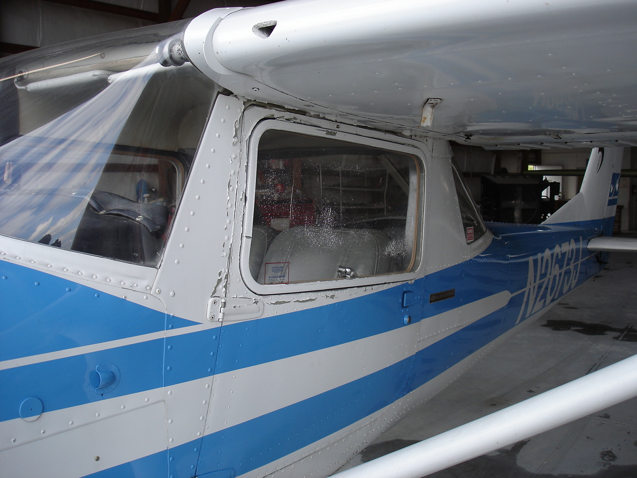
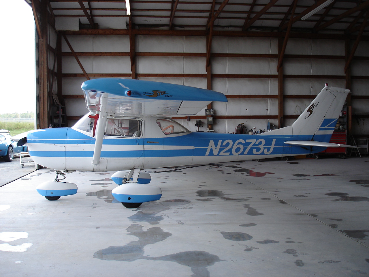
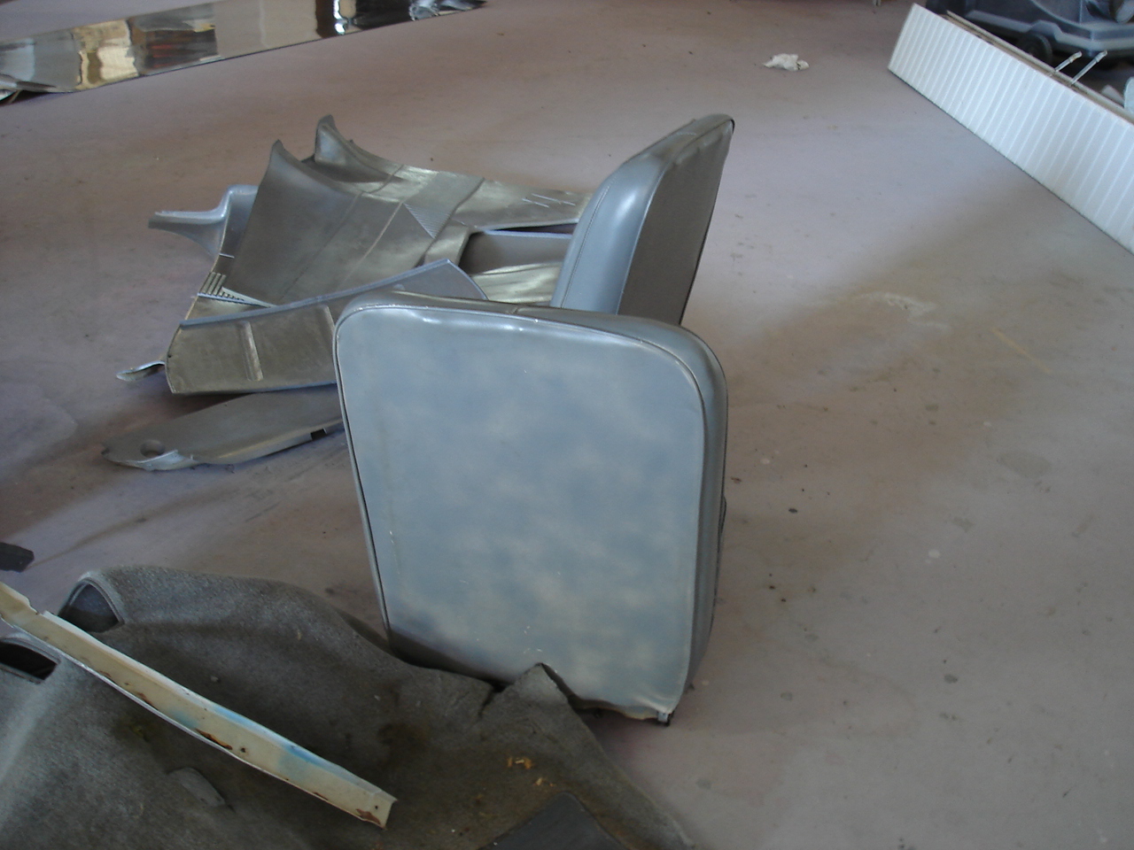
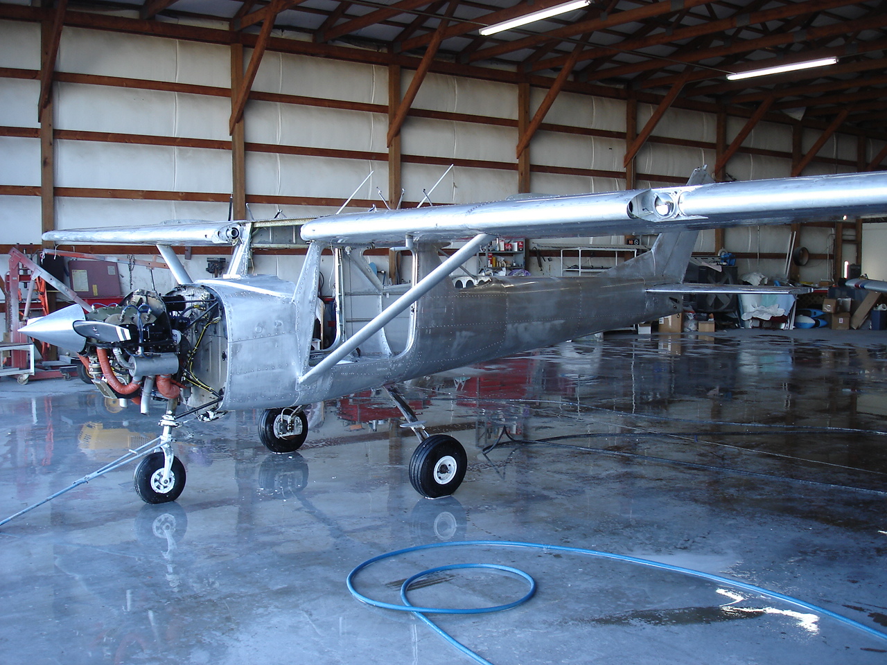
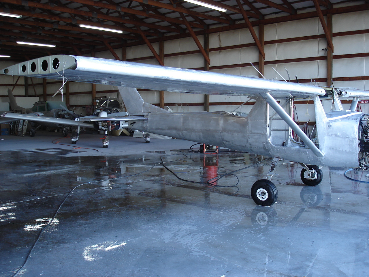
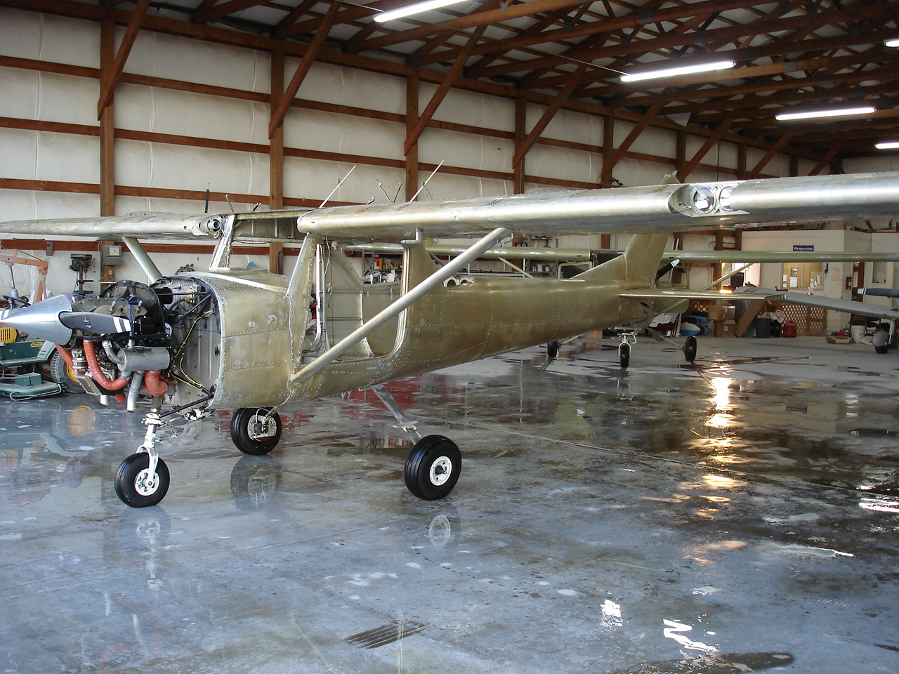
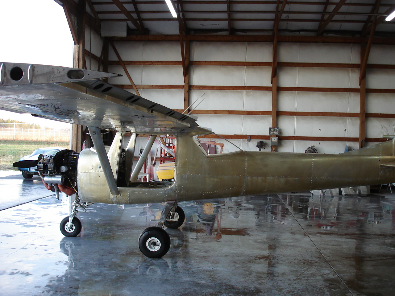
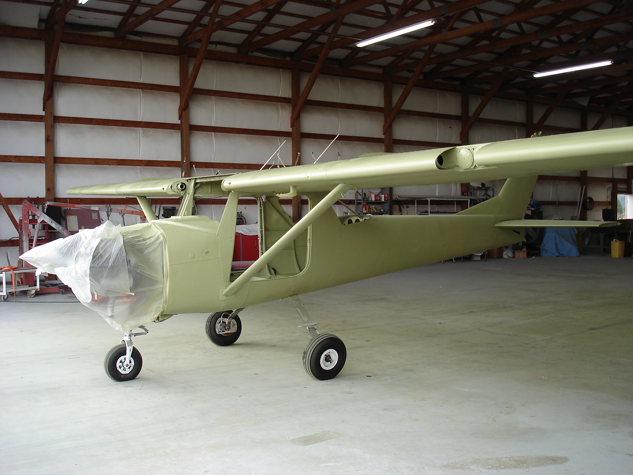
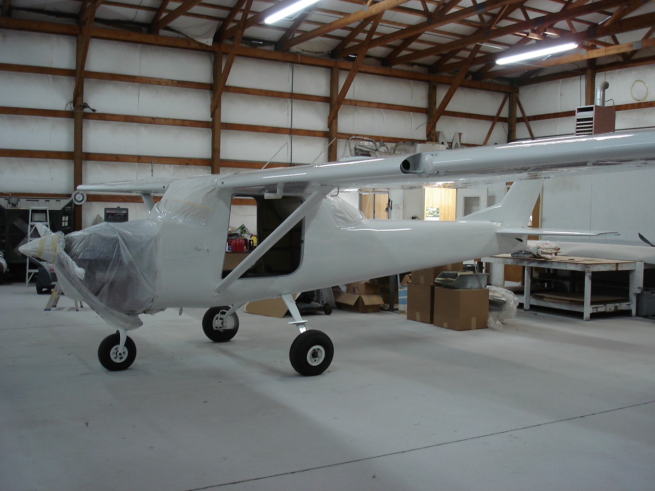
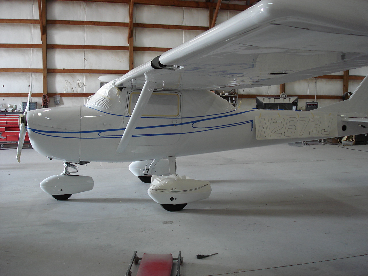
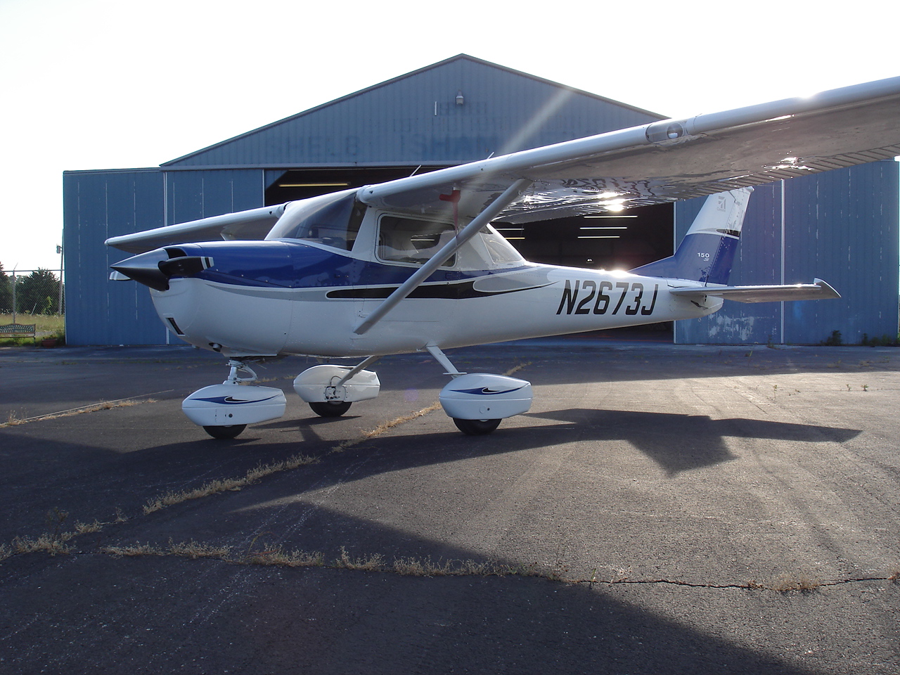
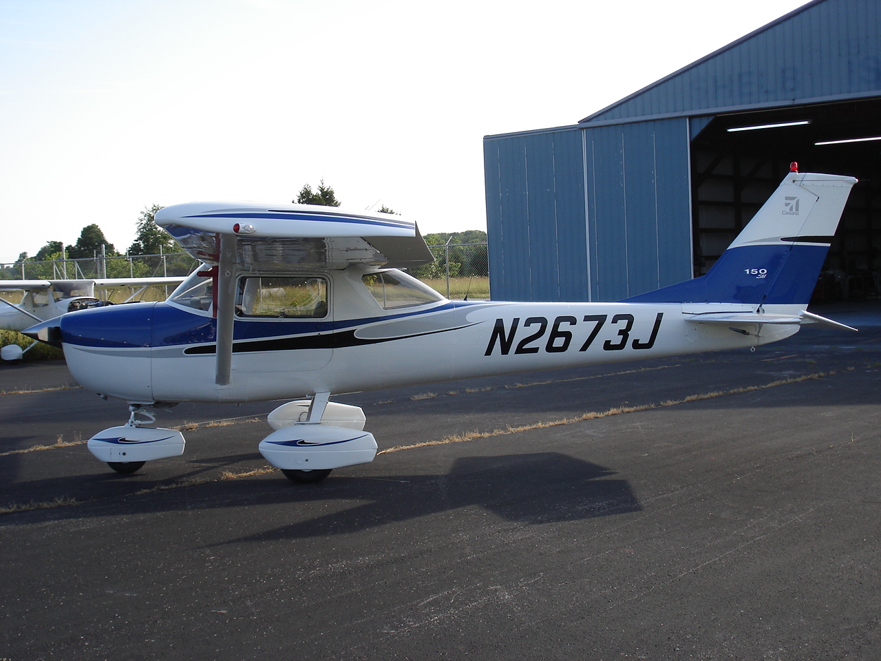
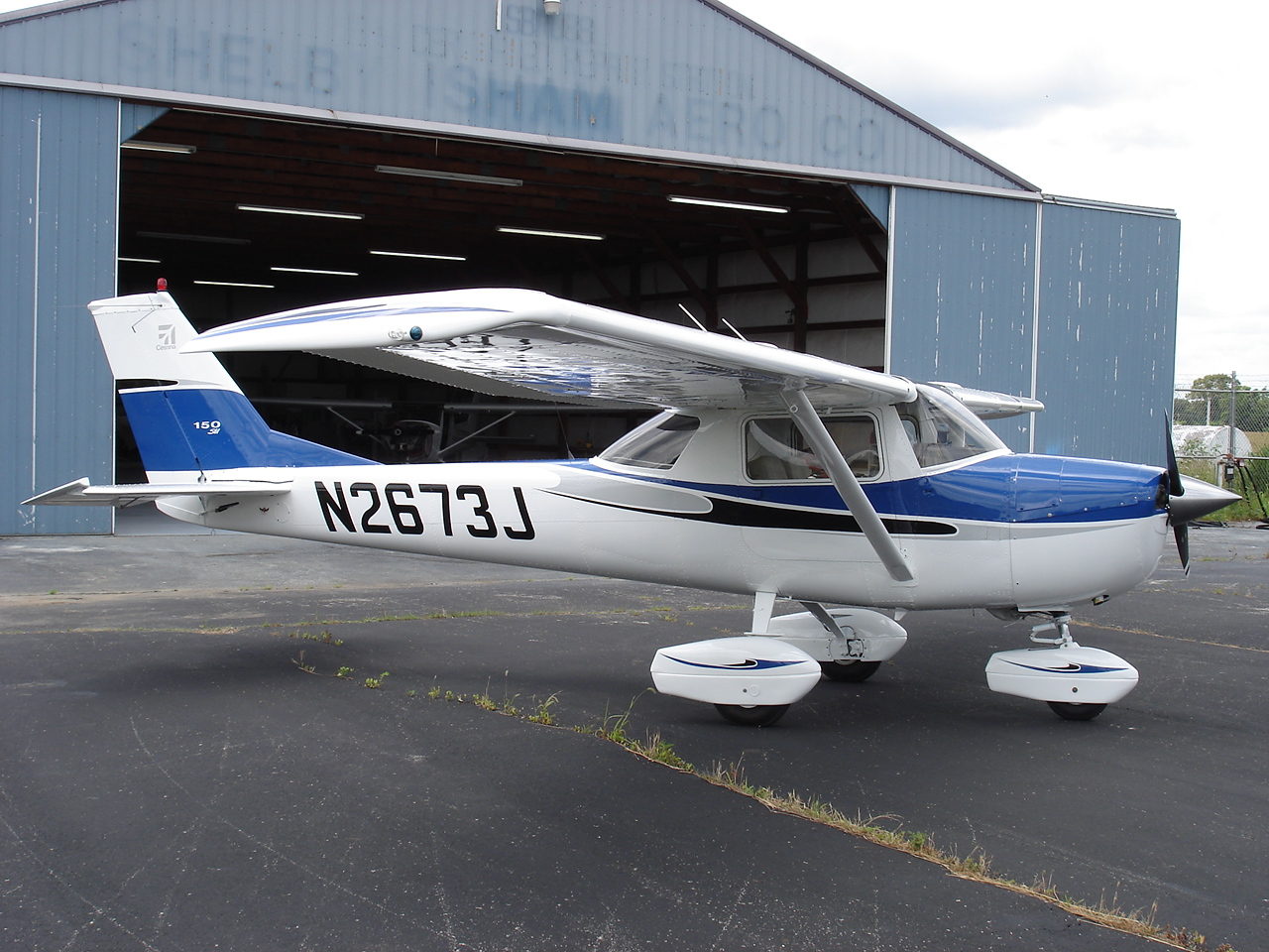
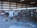
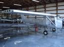
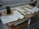
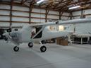
Here are the initial photos of 2673J. A very nice looking airplane overall, but in need of some work here and there.
N2673J
Menu
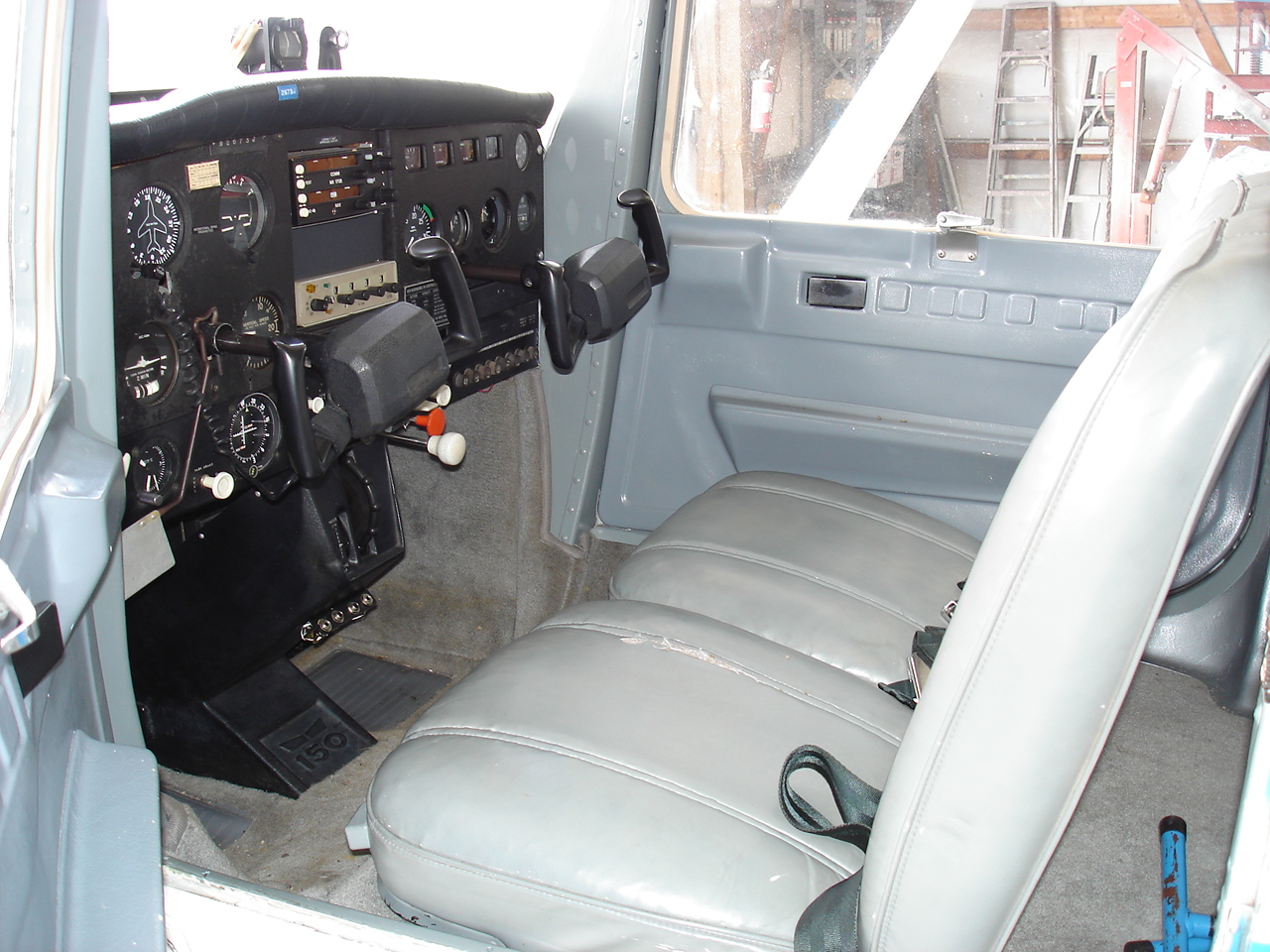
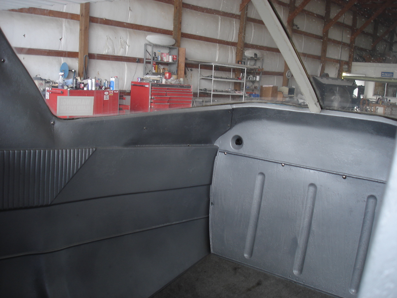
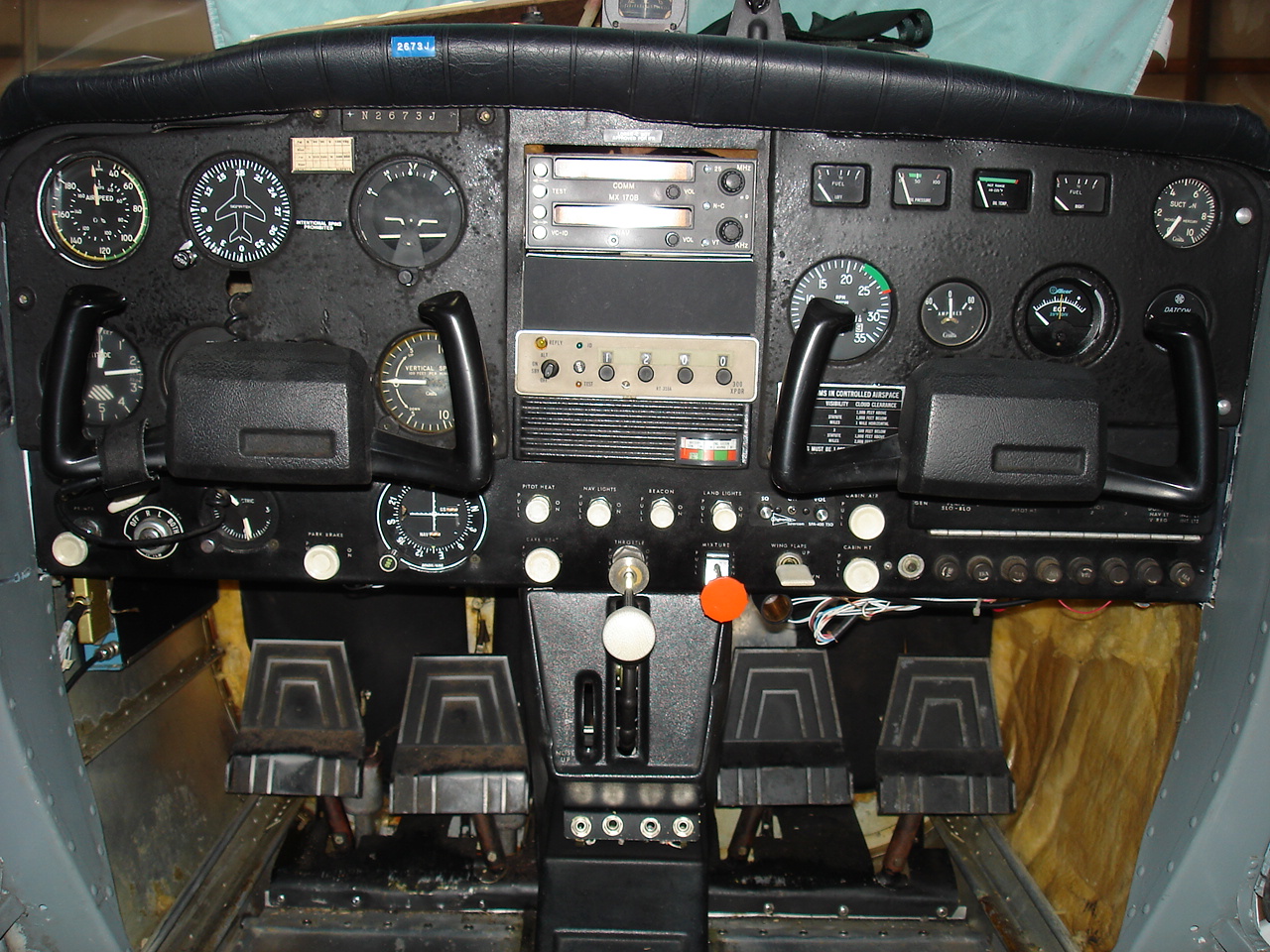
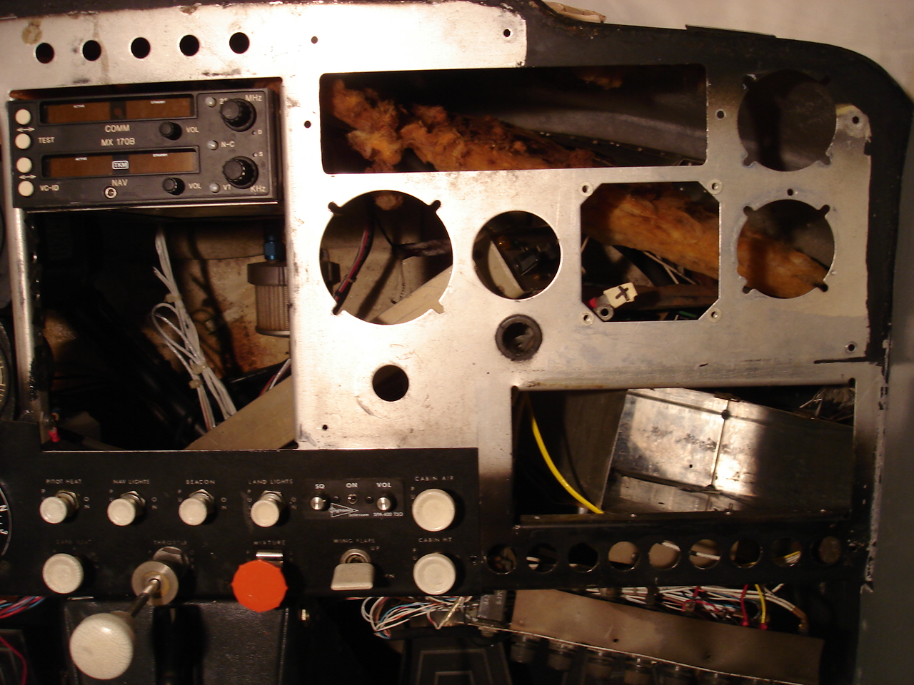
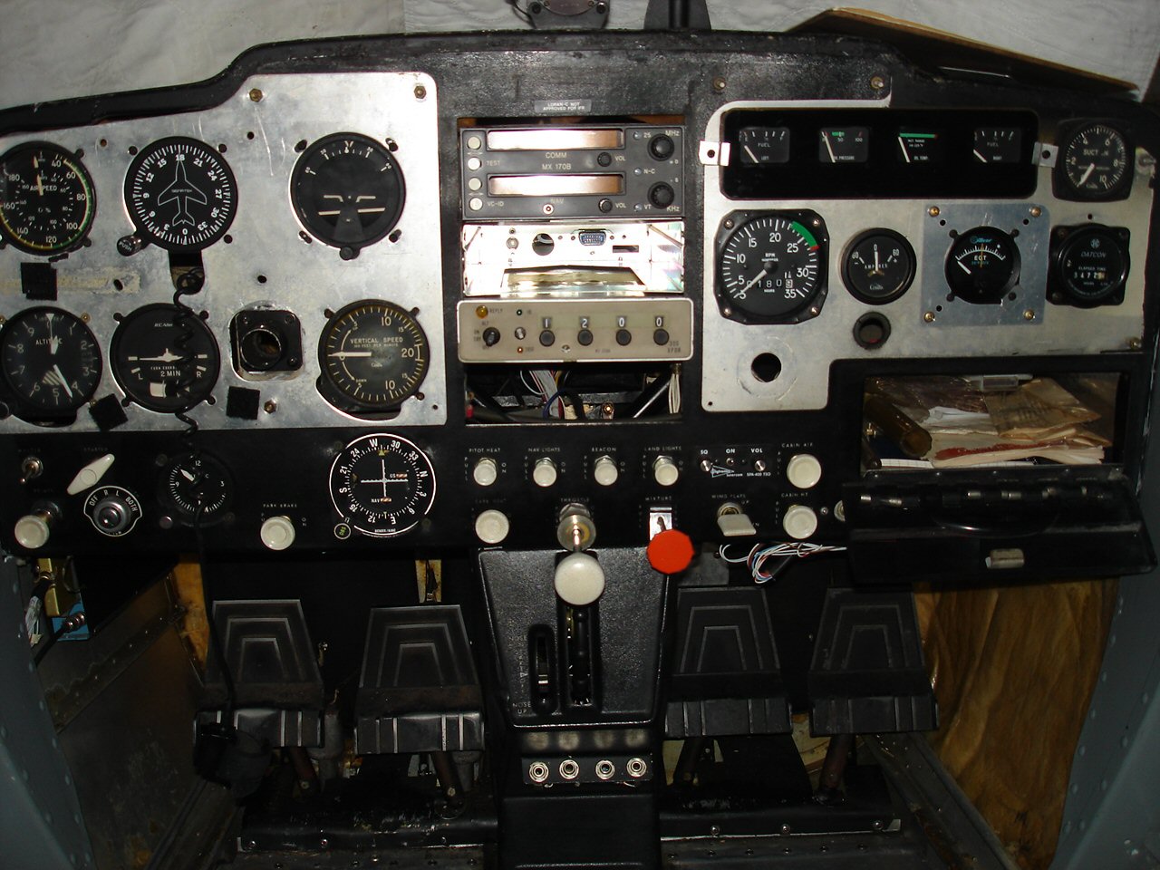
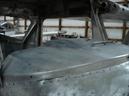
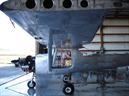
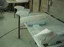
The plastics have previously been painted with a brush with what looks like aluminum colored metal paint. The door posts and jambs have been brush painted very heavily with battleship grey. Even the top of the panel was brush painted with flat black. All this will be remedied by replacing the plastics with new, complete strip and repaint of the interior and installation of a new headliner and all new soft goods inside. I don't know what's up with the eyebolt on top of the panel, but that's coming out too.
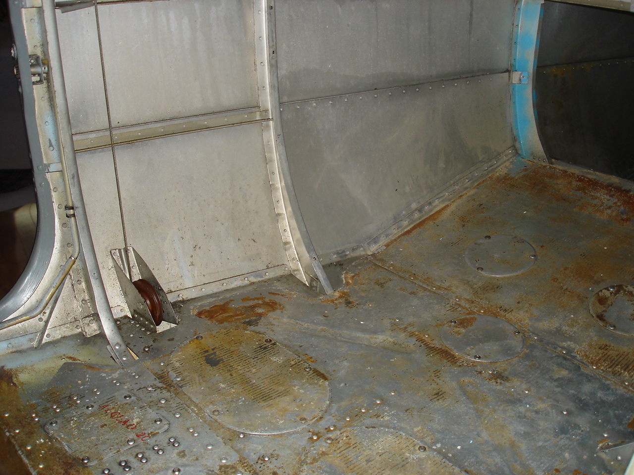
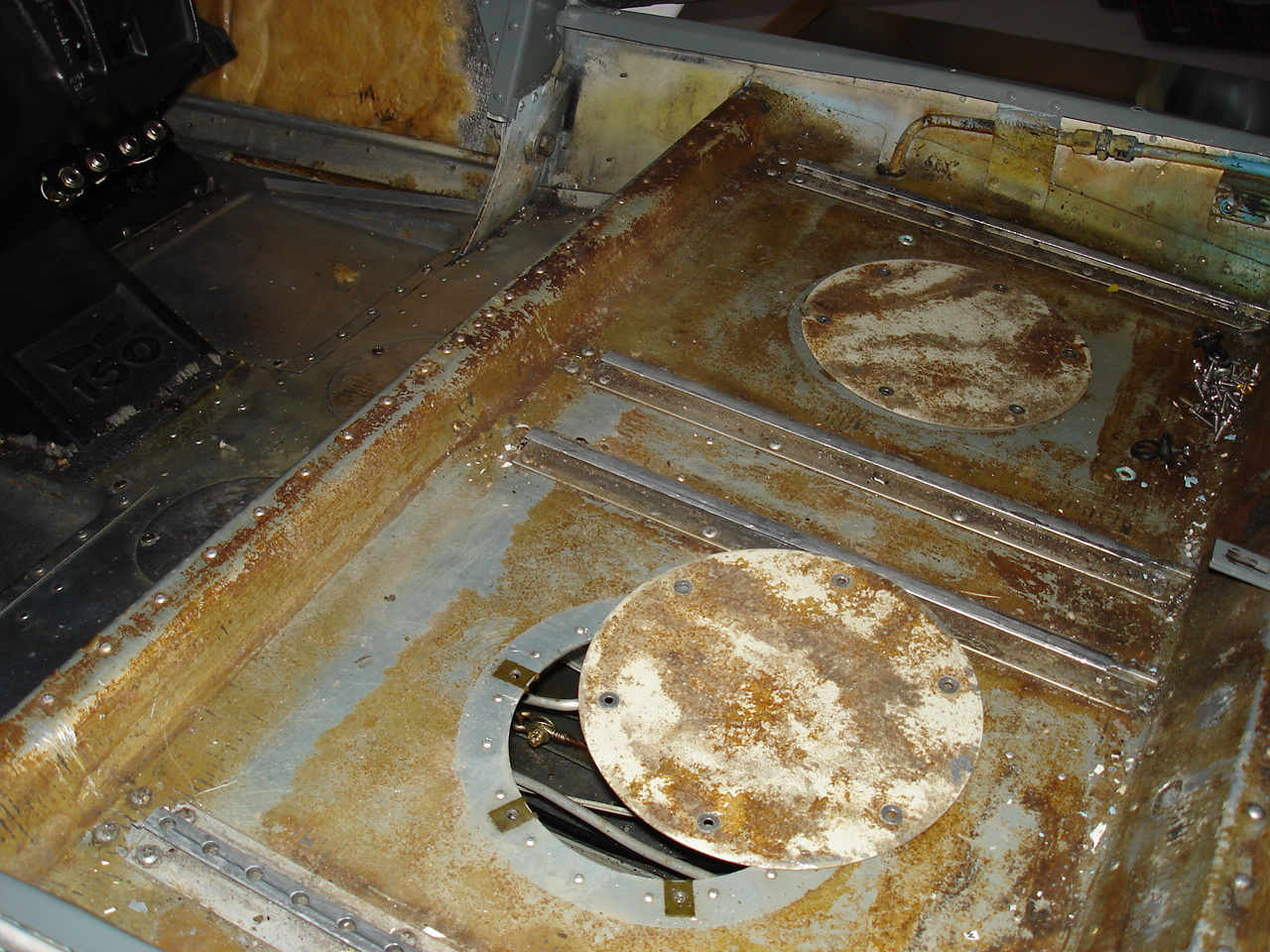
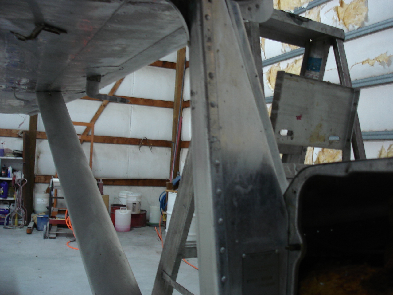
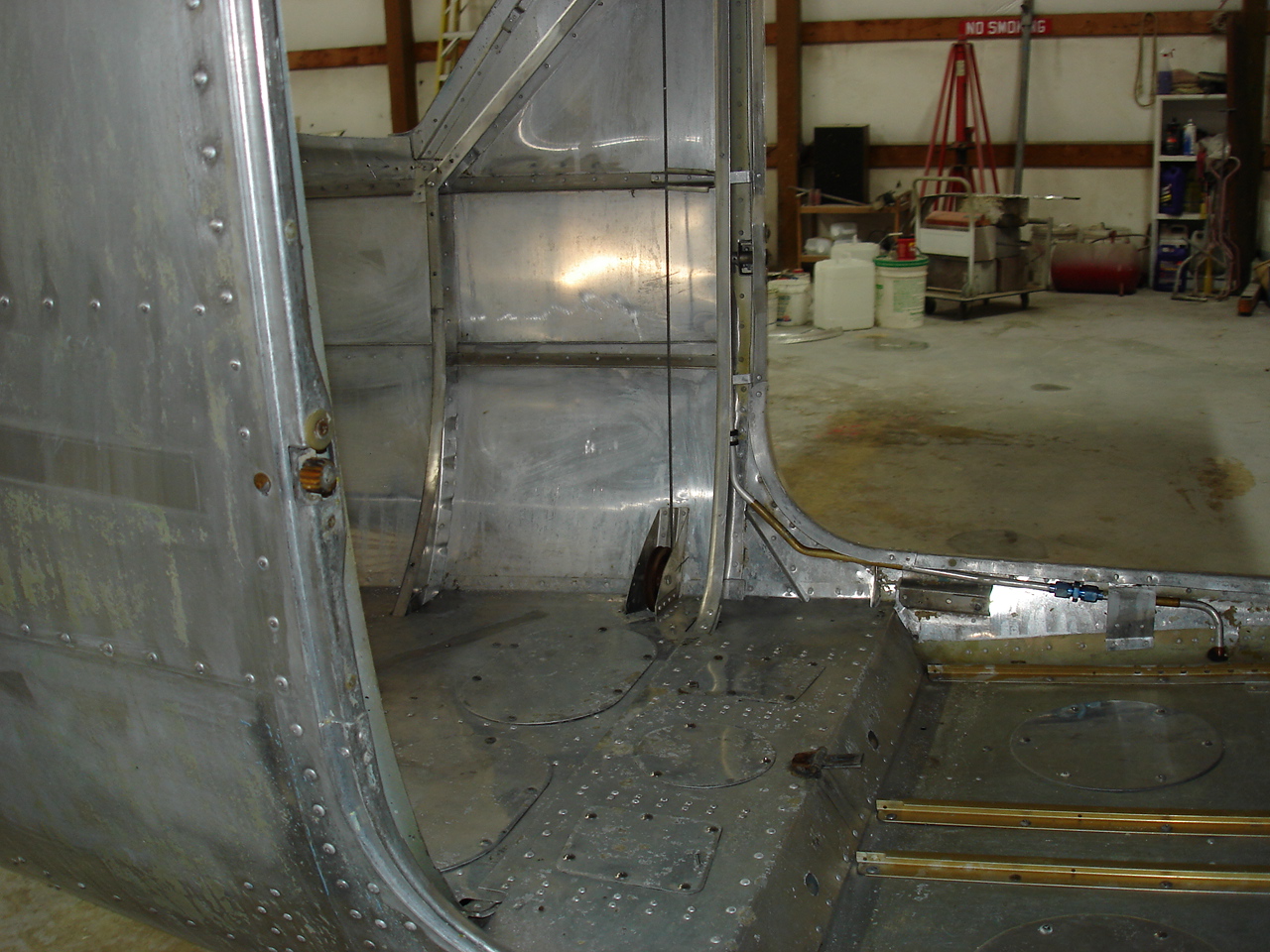
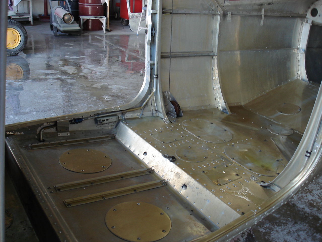
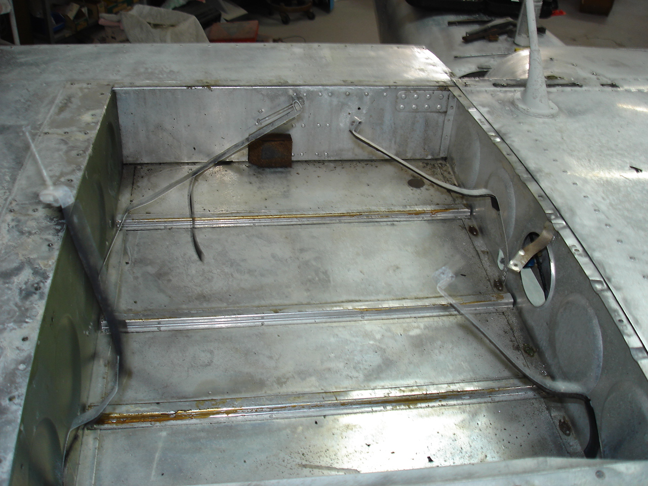
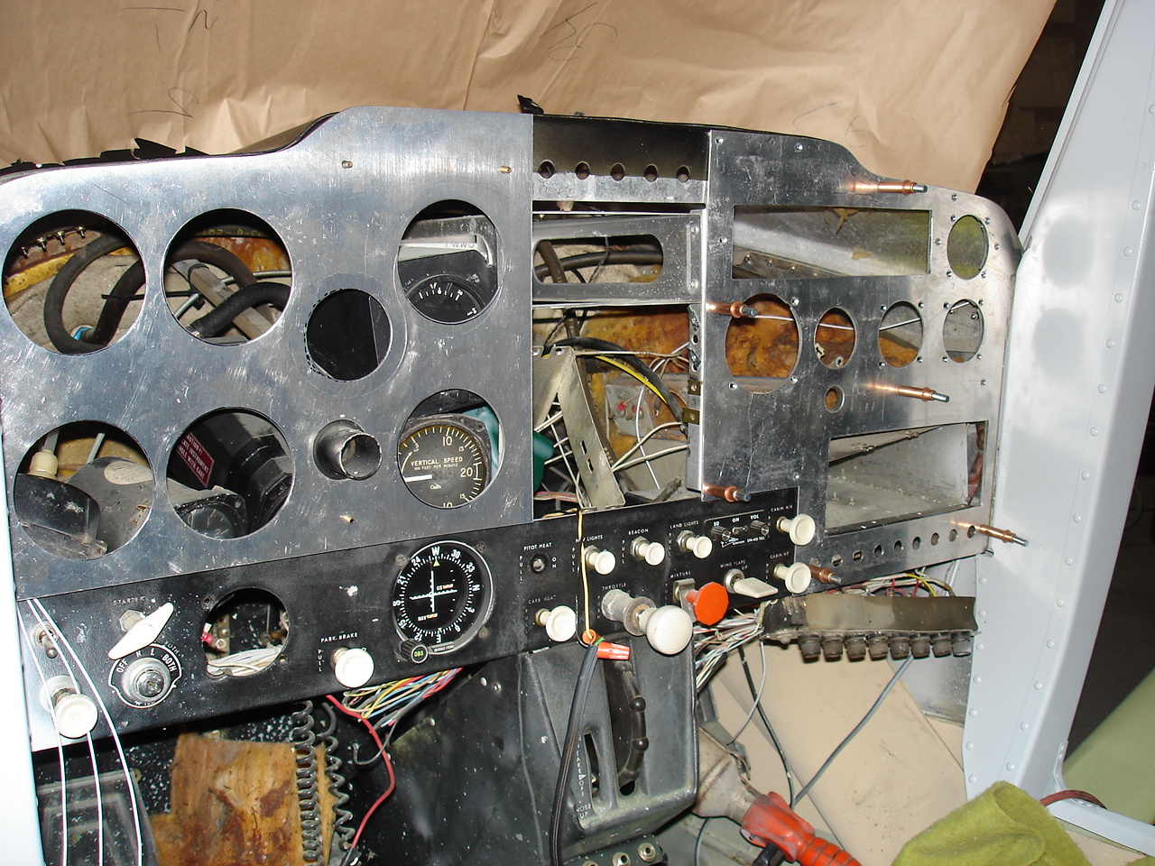
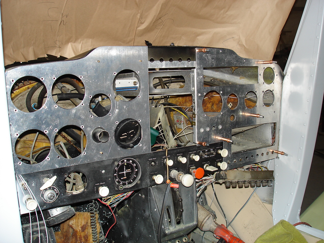
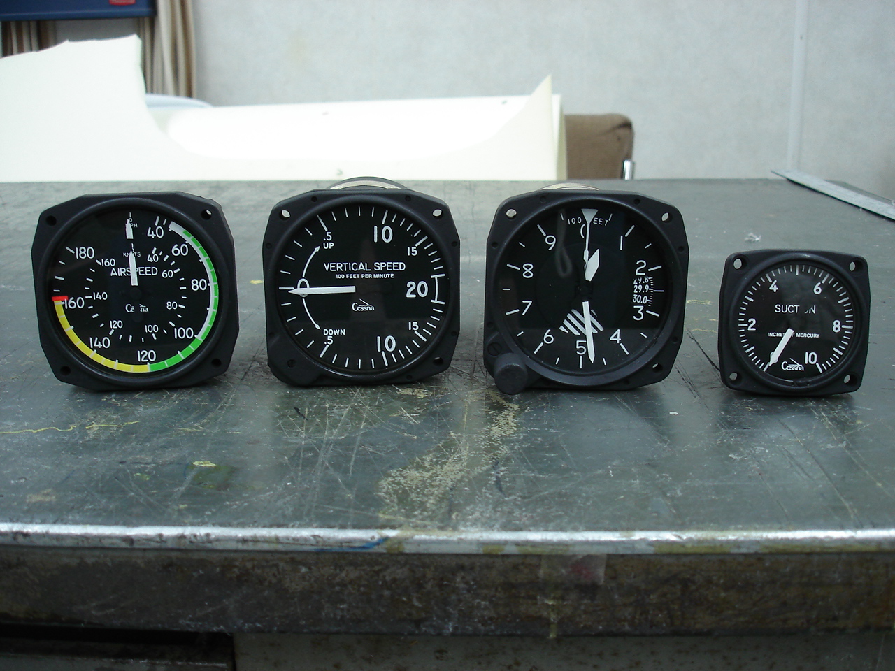
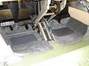
Everything pretty much removed here which showed a pretty nasty inside. Seat rails look pretty beat and theres lots of glue, dirt, oil, etc. all over the floor and side walls. The flight controls are removed and show a good view of the amount of corrosion-preventative compound still leaking from the seams. Got most of the instruments out in preparation for the new custom instrument panel.
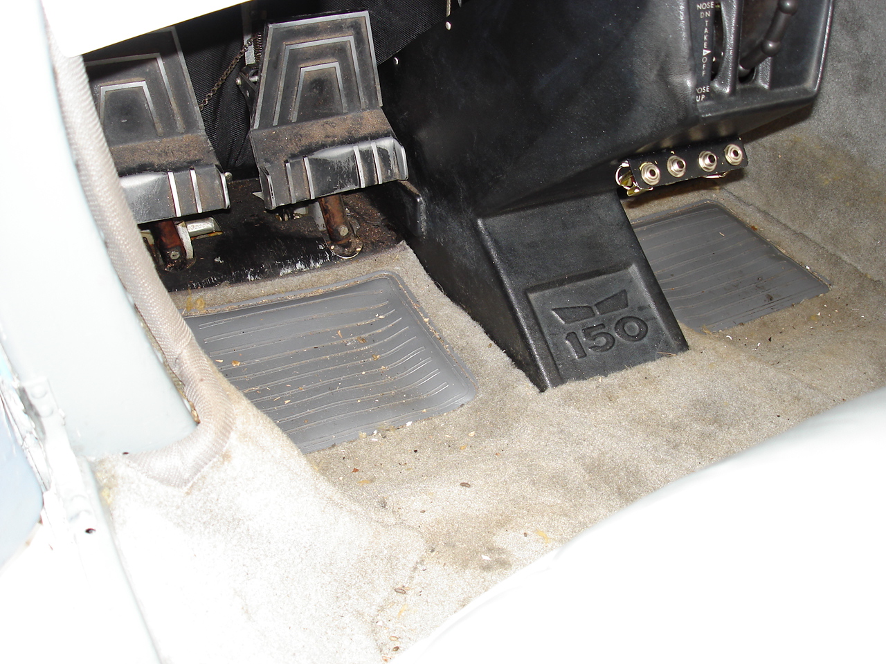
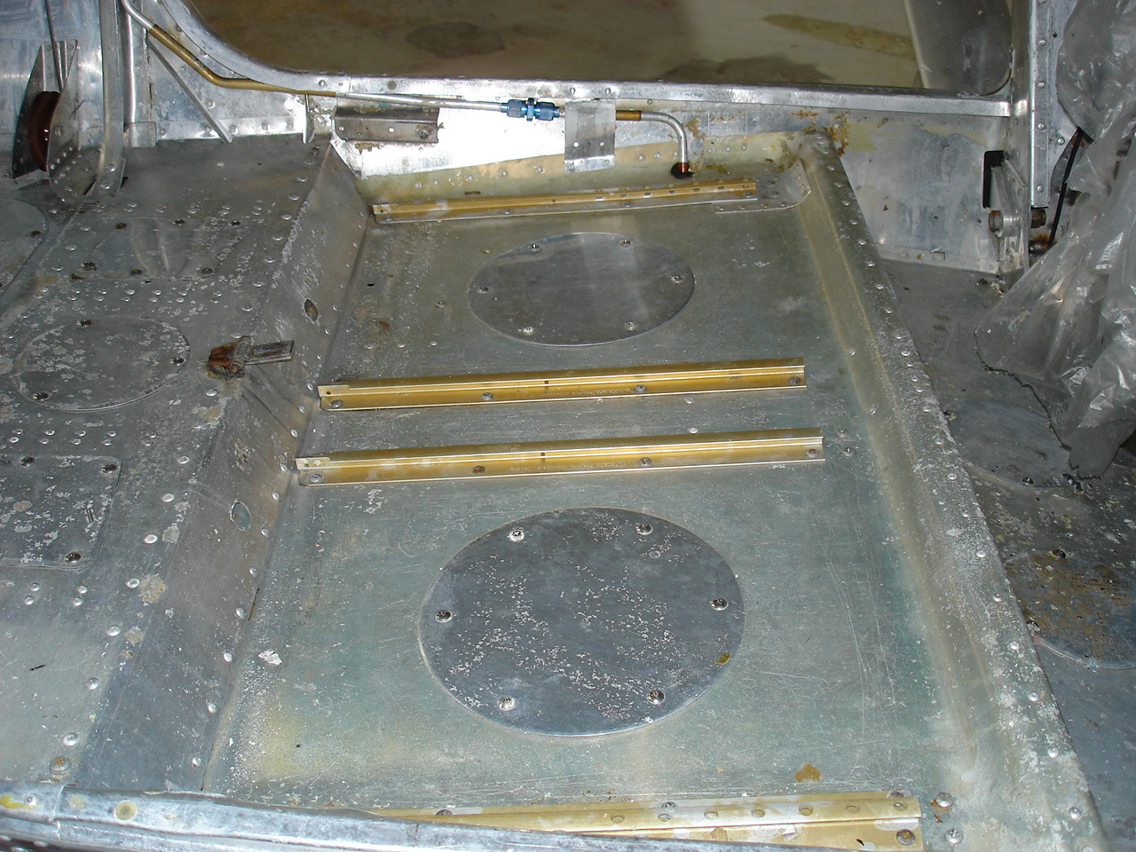
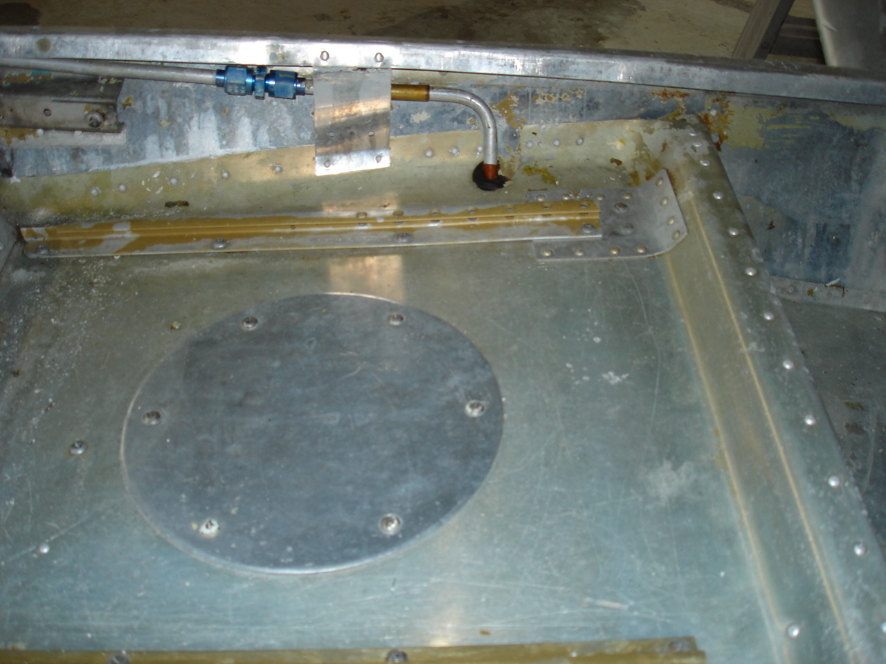
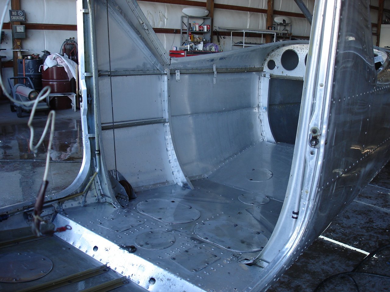
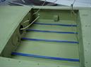
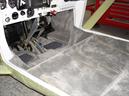
O.k., here we have the interior all cleaned up. Found a crack in the floor pan at the forward section of the pilot's seat rail. Made a small repair there which you can see in the last photo. This is actually pretty common in short rail 150s. Also, got a new set of seat rails installed. Lots and lots of cleaning here, as you can see.
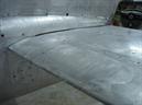
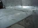
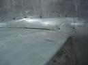

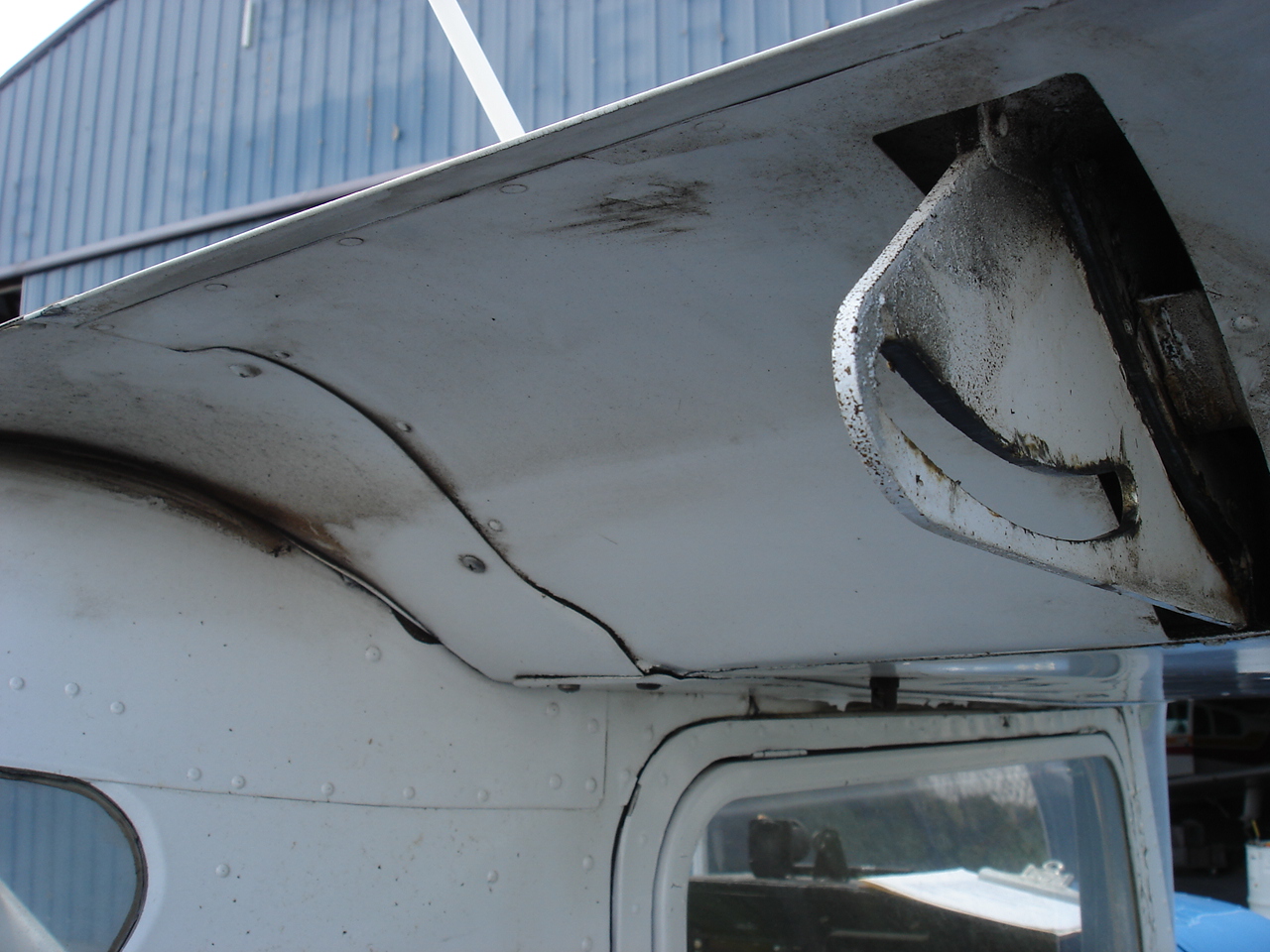
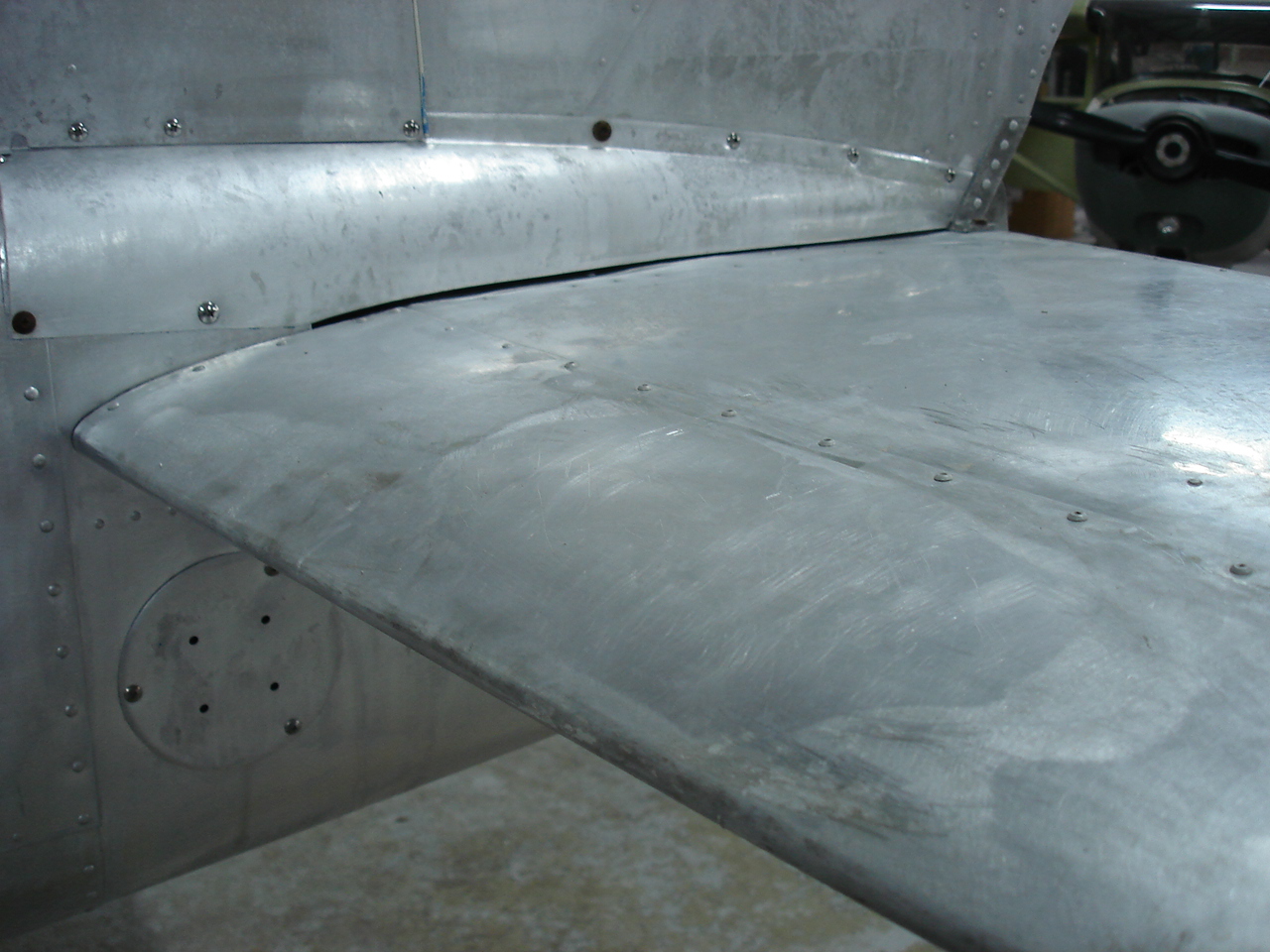
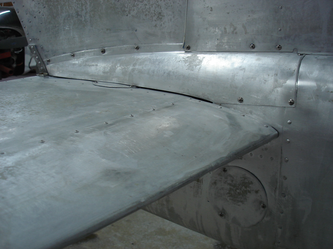
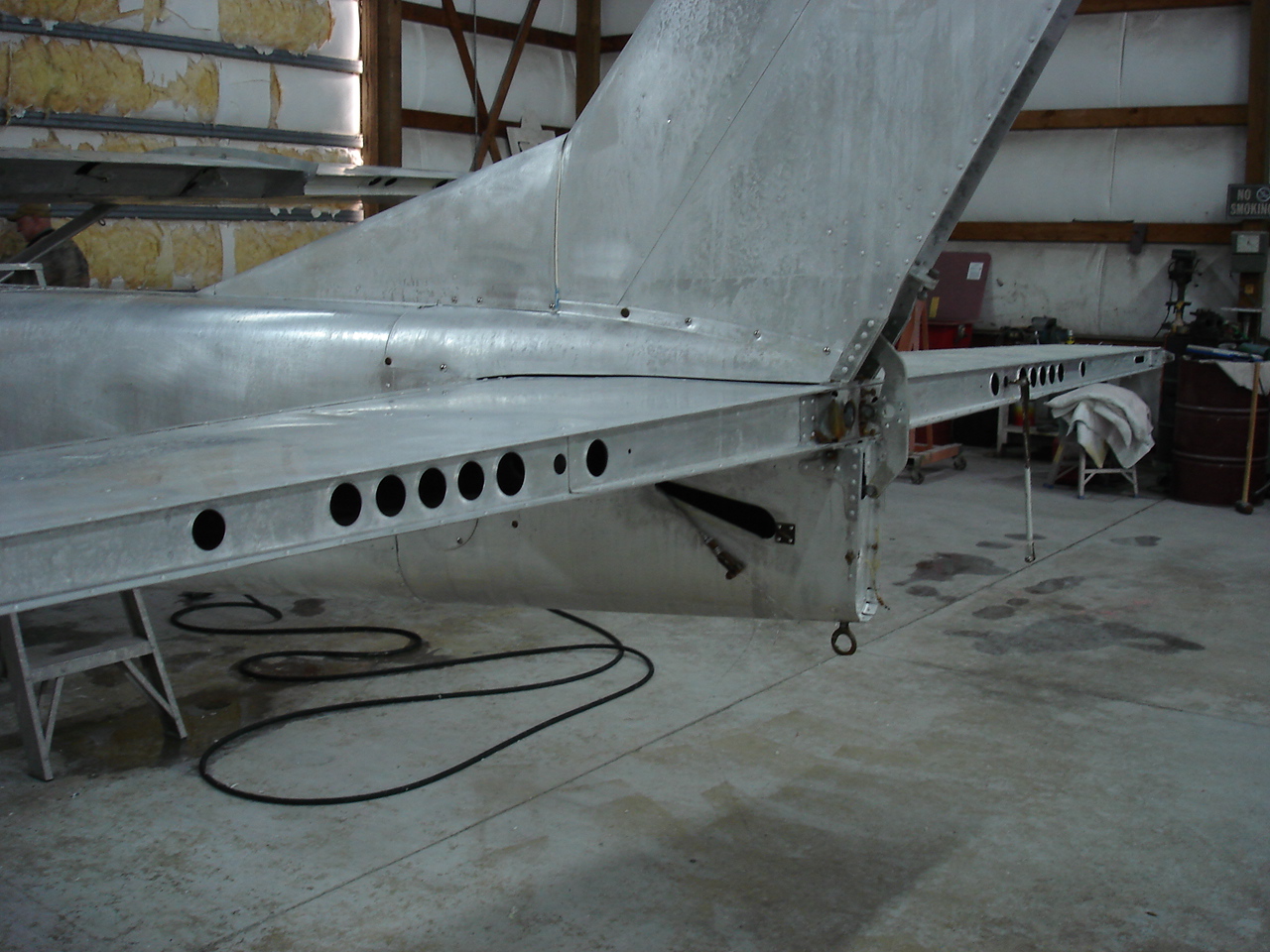
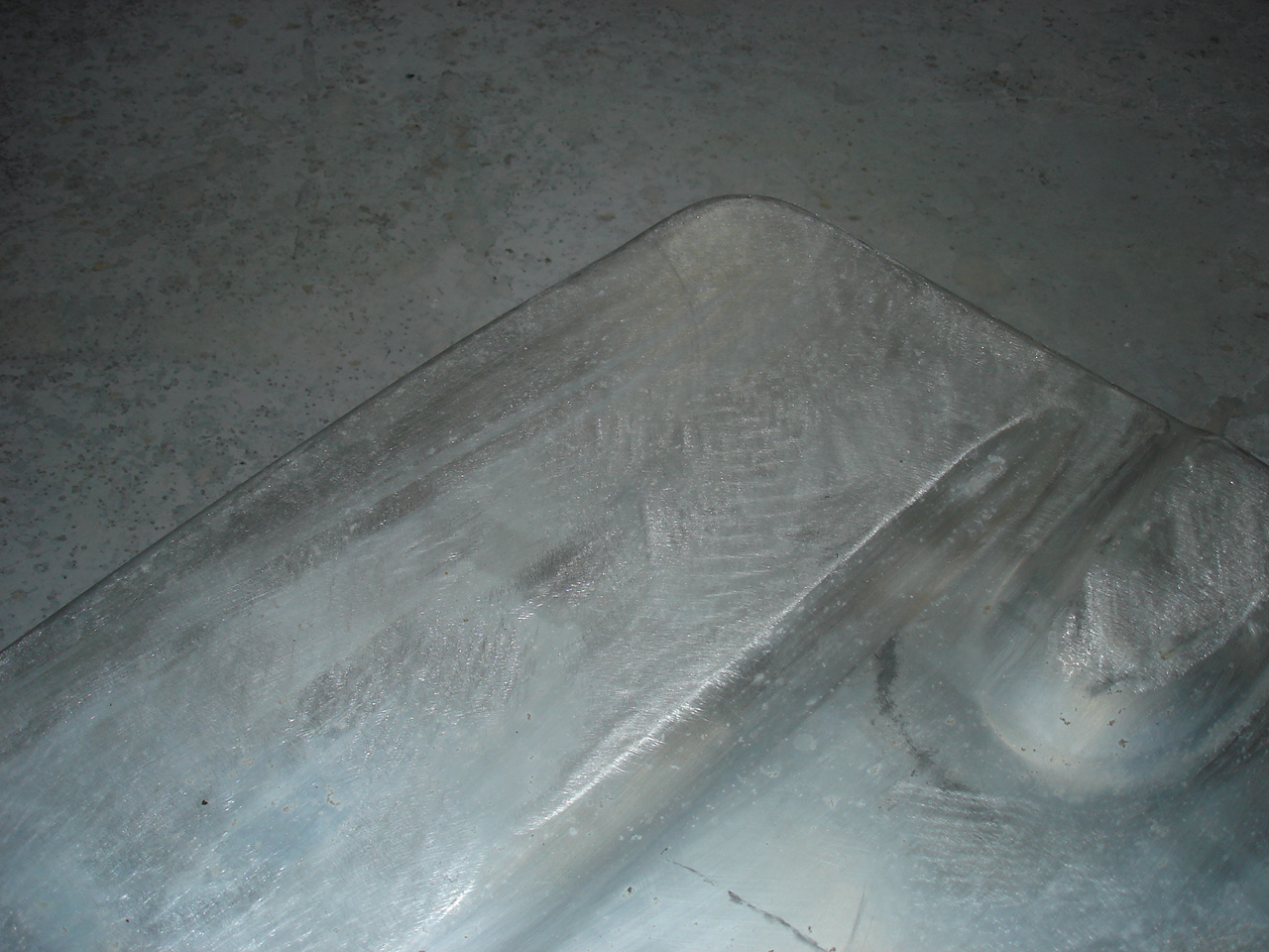
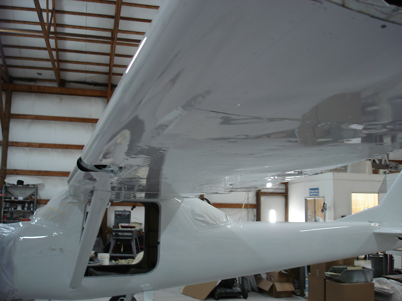
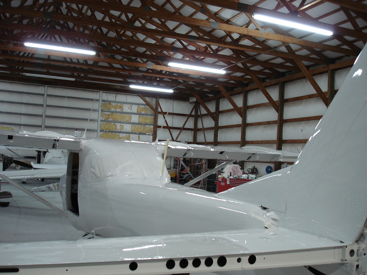
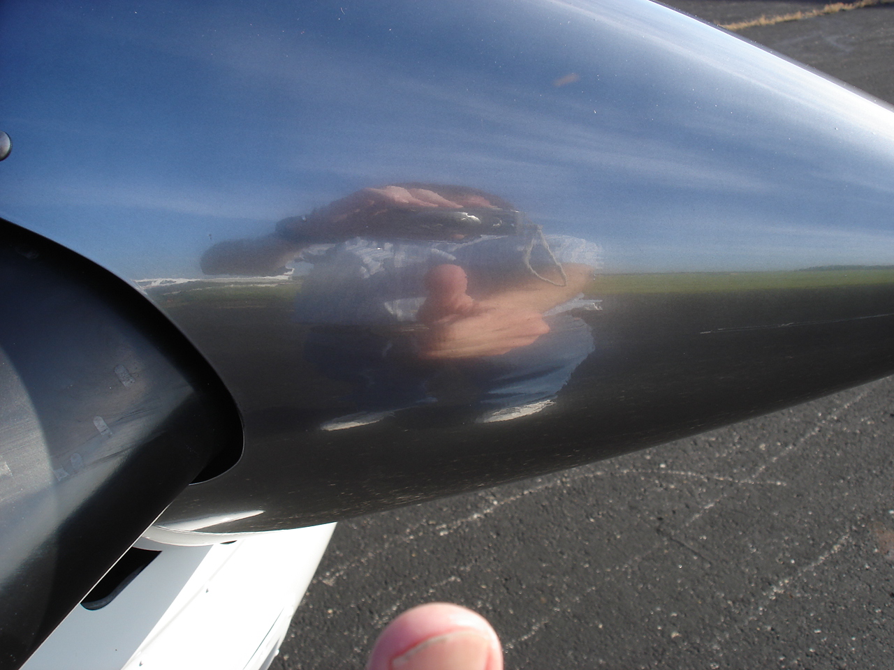
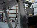
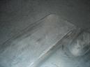
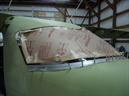
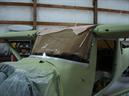
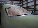
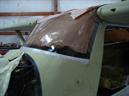
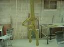
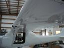
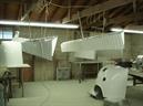
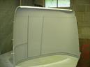
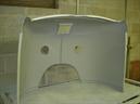
This is where I got worried. The inboard leading edge of the horizontal had two huge dents in the top. One on each side. This was where people had repeatedly pushed down on the tail to turn the airplane around. Apparently, somebody decided that the appropriate fix was to fill these dents with bondo. I hate that during my worried haste, I forgot to get a picture of all the bondo that I dug out of here, but you can plainly see where it was. Anyway, its marked by a dark ring on the metal along the leading edge. Yes, it was "that" big. The leading edge rivets were almost sanded away at this point. From all indications, so far the horizontal is o.k. After digging the bondo out, we drilled out some of the leading edge rivets and rolled the sheet metal back out from the backside, then riveted it back down to the spar. Needless to say, I'm relieved that this worked and the two photos show the results. I'm very proud of this and I'm hopeful that the rest of it is o.k. I can guarantee you this was a helluva lot cheaper than buying another stabilizer !
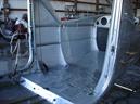
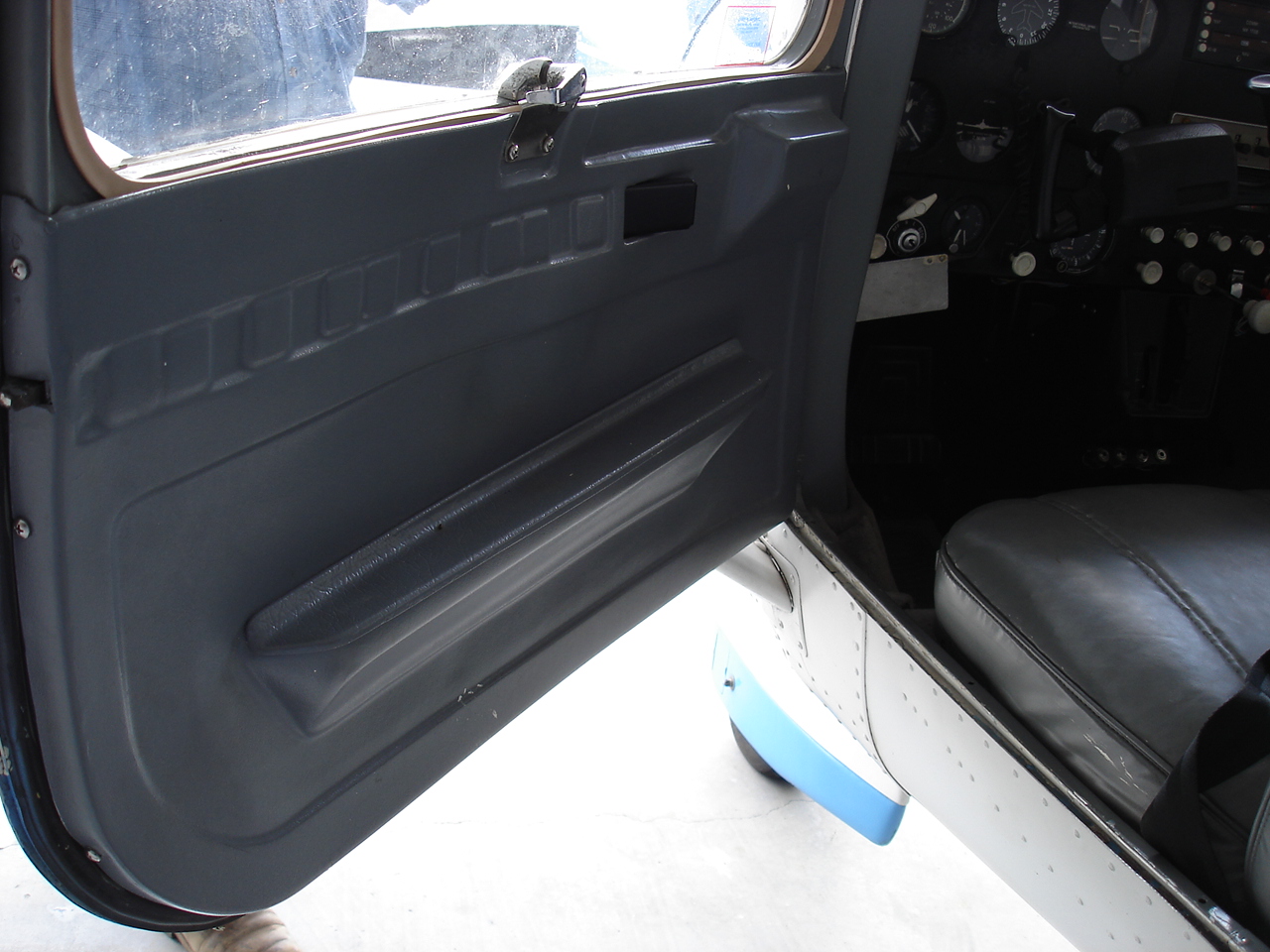
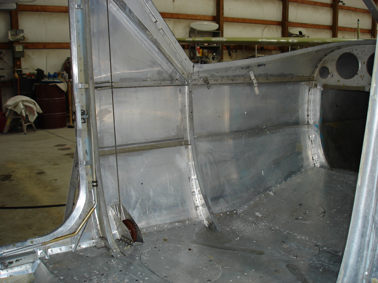
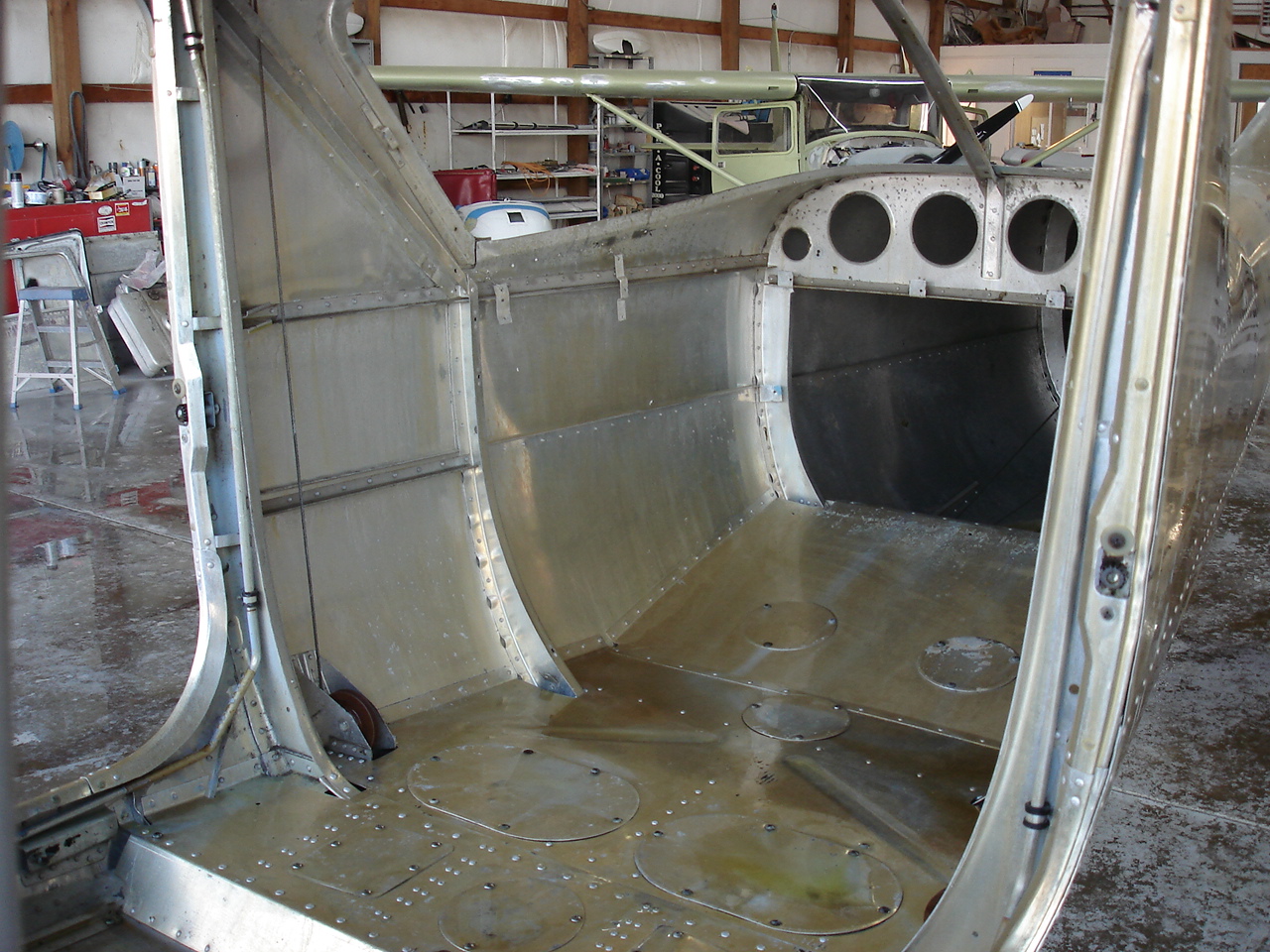
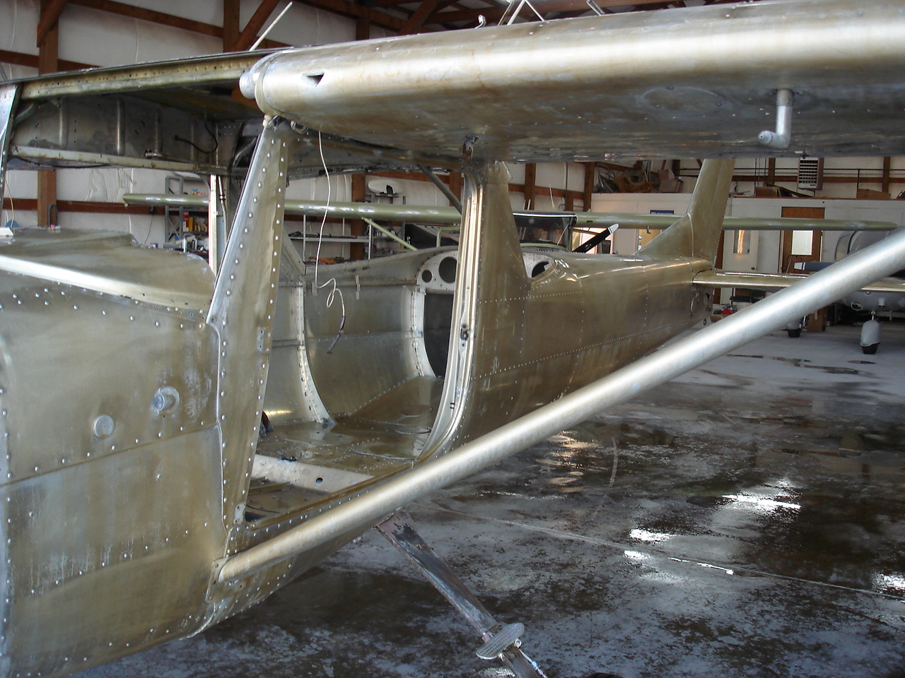
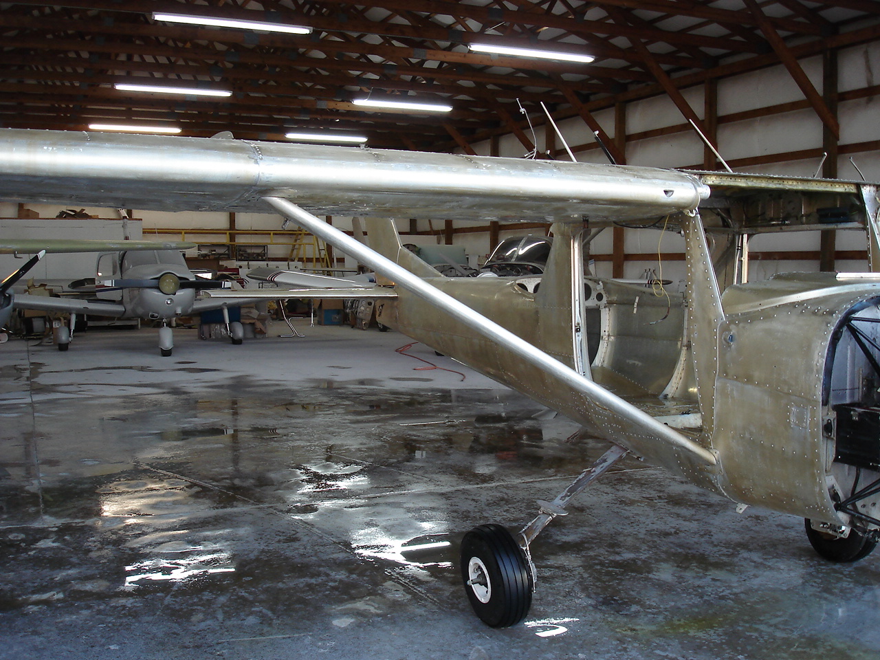
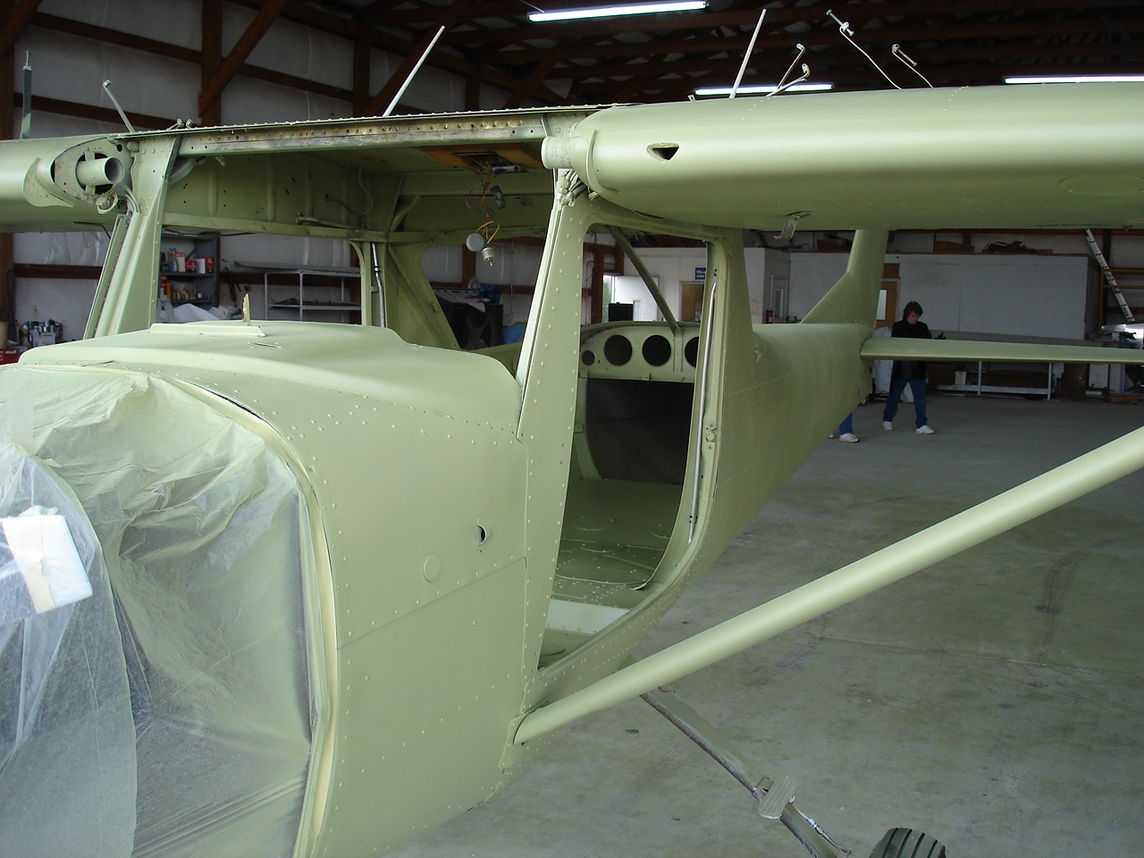
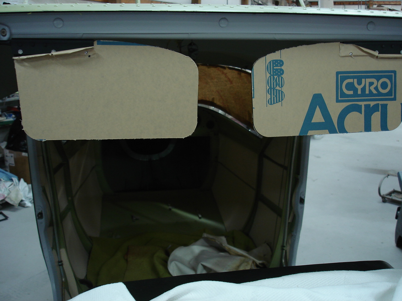
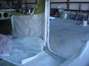
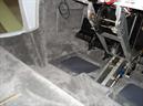
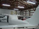
These are just some general photos of how it cleaned up. Got all the windows removed and pretty much everything down to where I want it. I still can't believe there was so much paint on those door posts, let alone the fact that they piled it on with a paint brush. That's all about to change ! The last few photos here show what it looks like right after the acid etch process. Raw, clean, and shiny just like we want it.
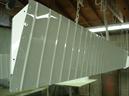
These are some shots of it after the alodyne. I went ahead and did the inside too. This will give us maximum adhesion of the epoxy corrosion primer and help give the maximum in corrosion protection.
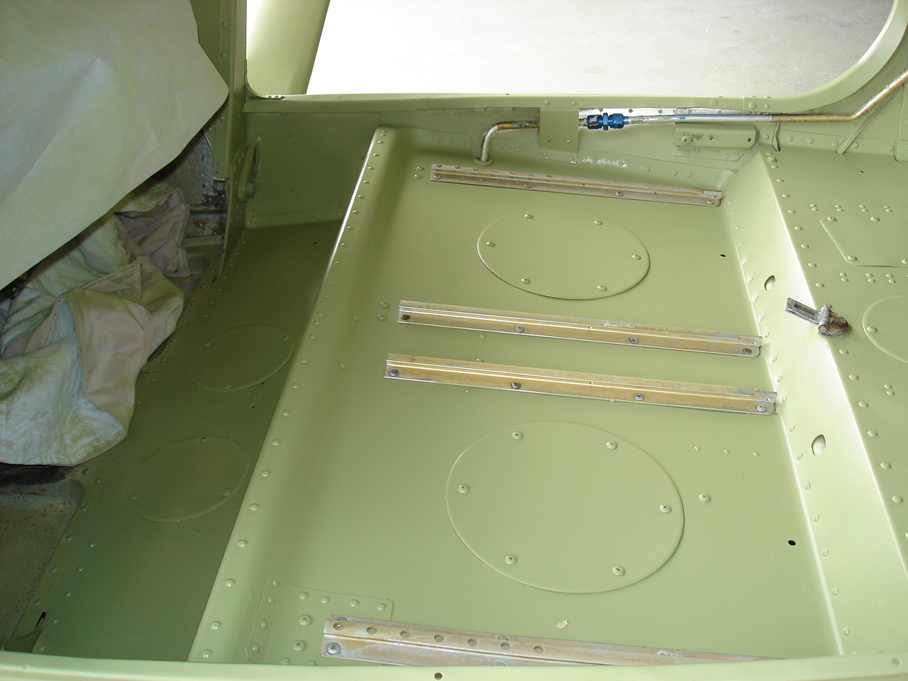
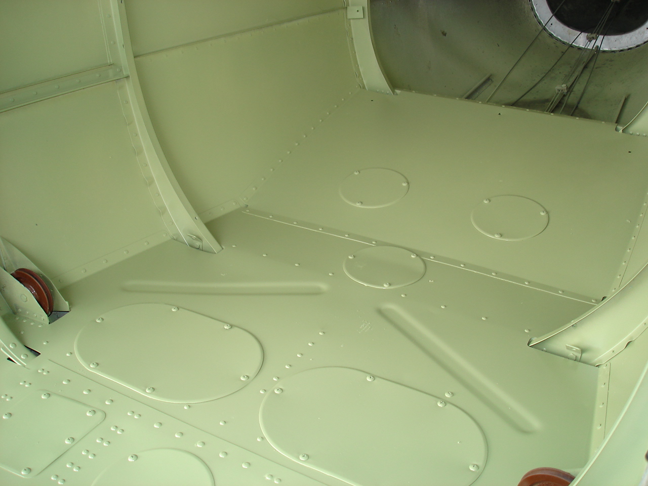
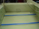
Now we start to see a little progress for the amount of trouble. Got the epoxy corrosion primer done. I'm going to leave the floor boards just like this. Man, am I happy with the way this looks. I did interior sides, door jambs, everything. The exterior is now ready to sand down in preparation for the window install and the painting process.
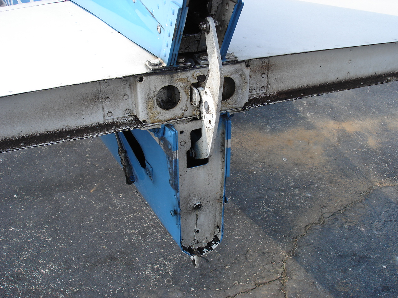
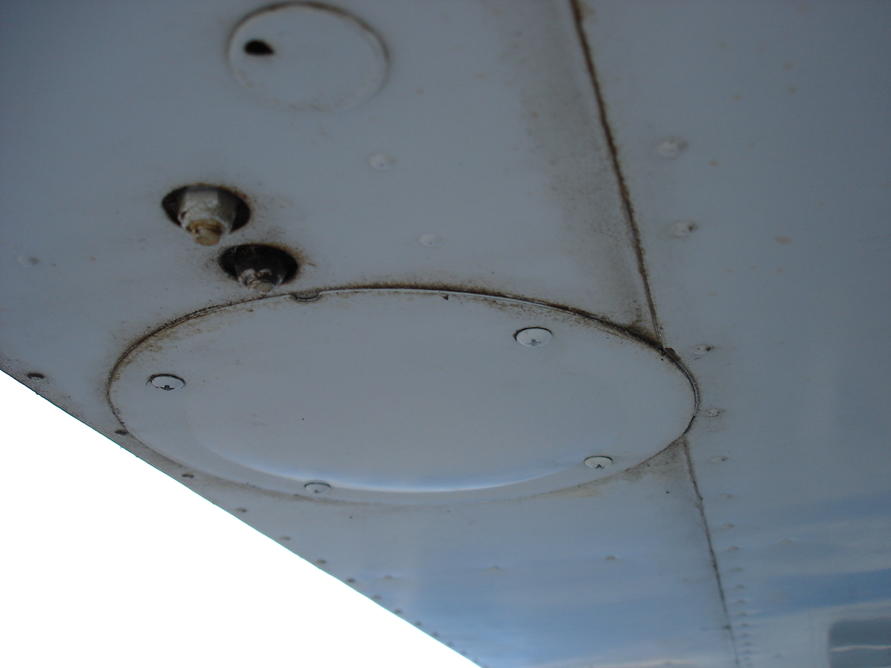
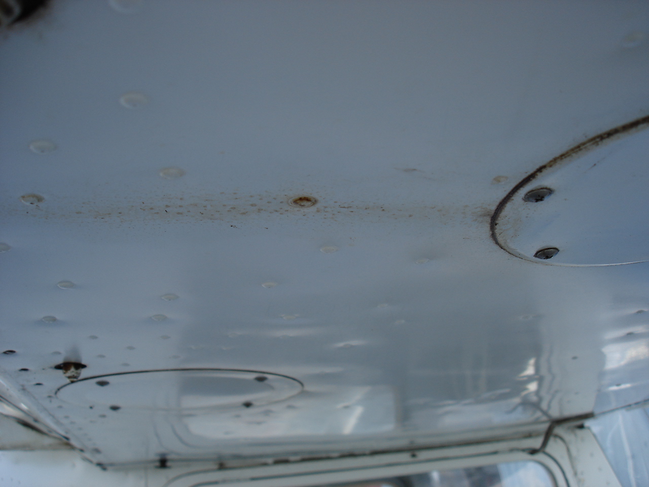
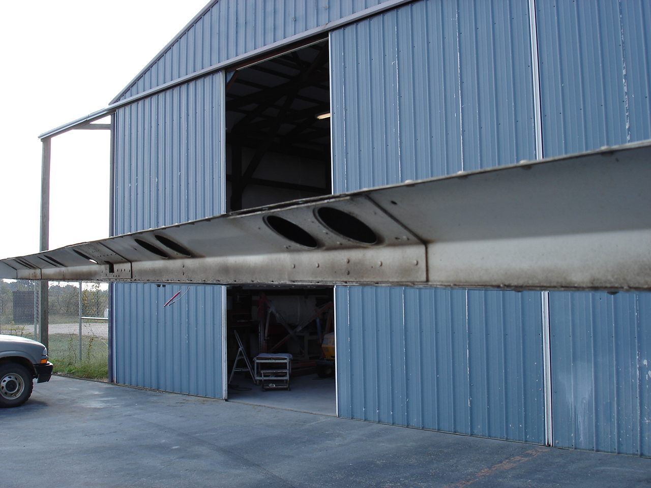
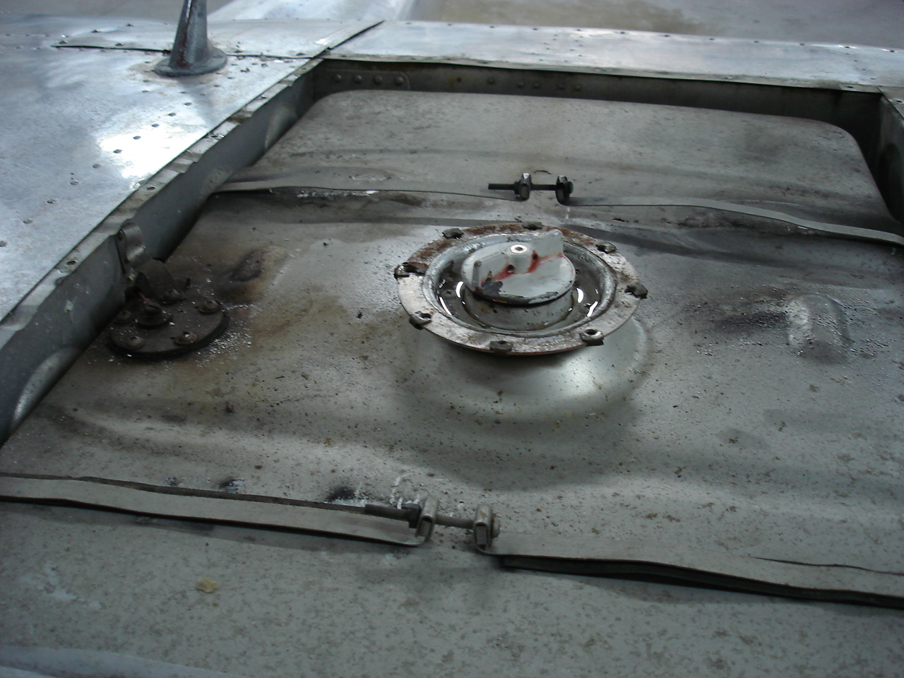
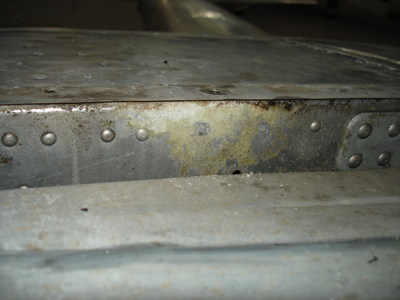
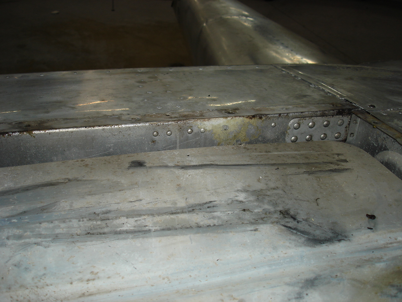
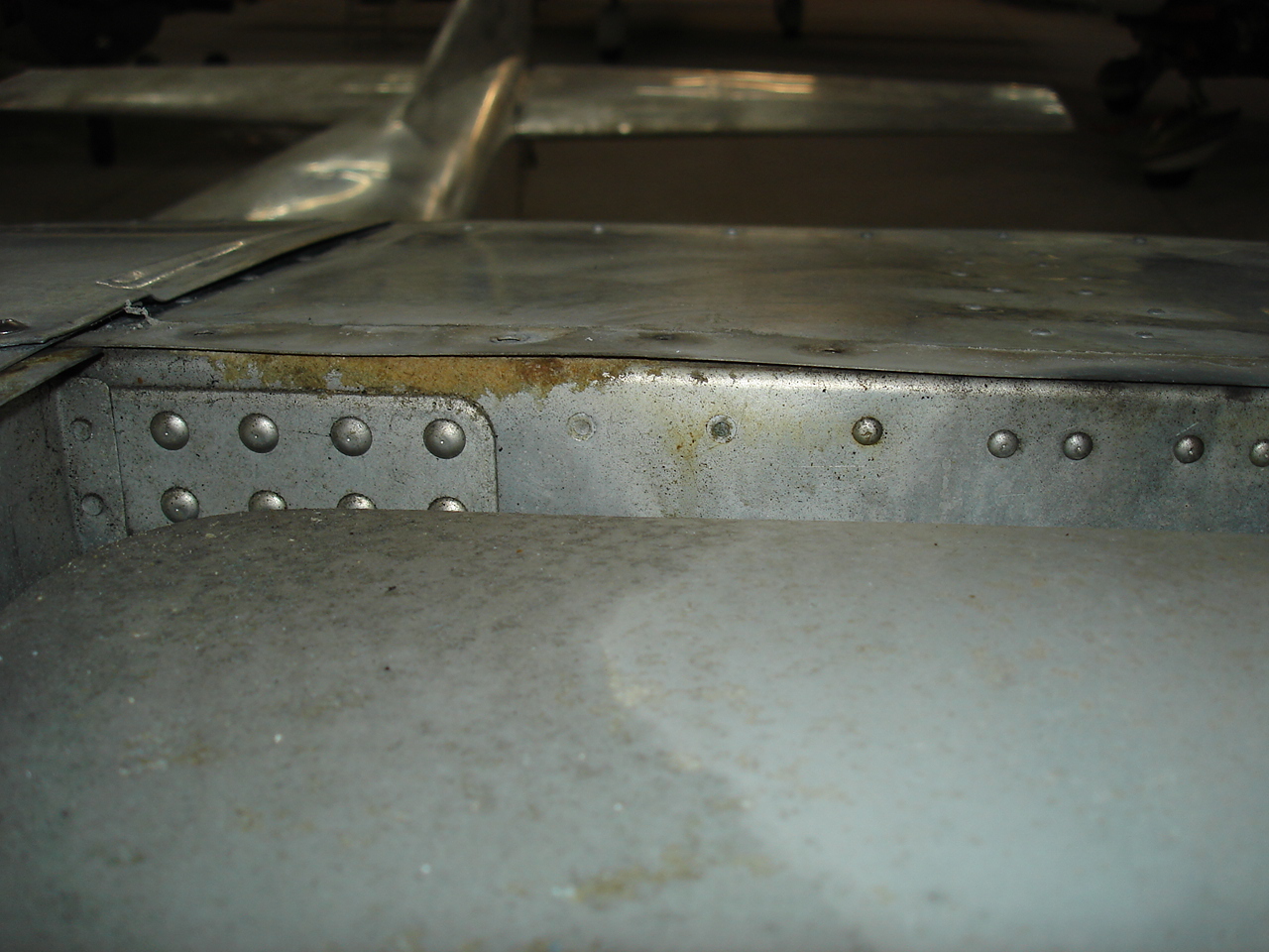
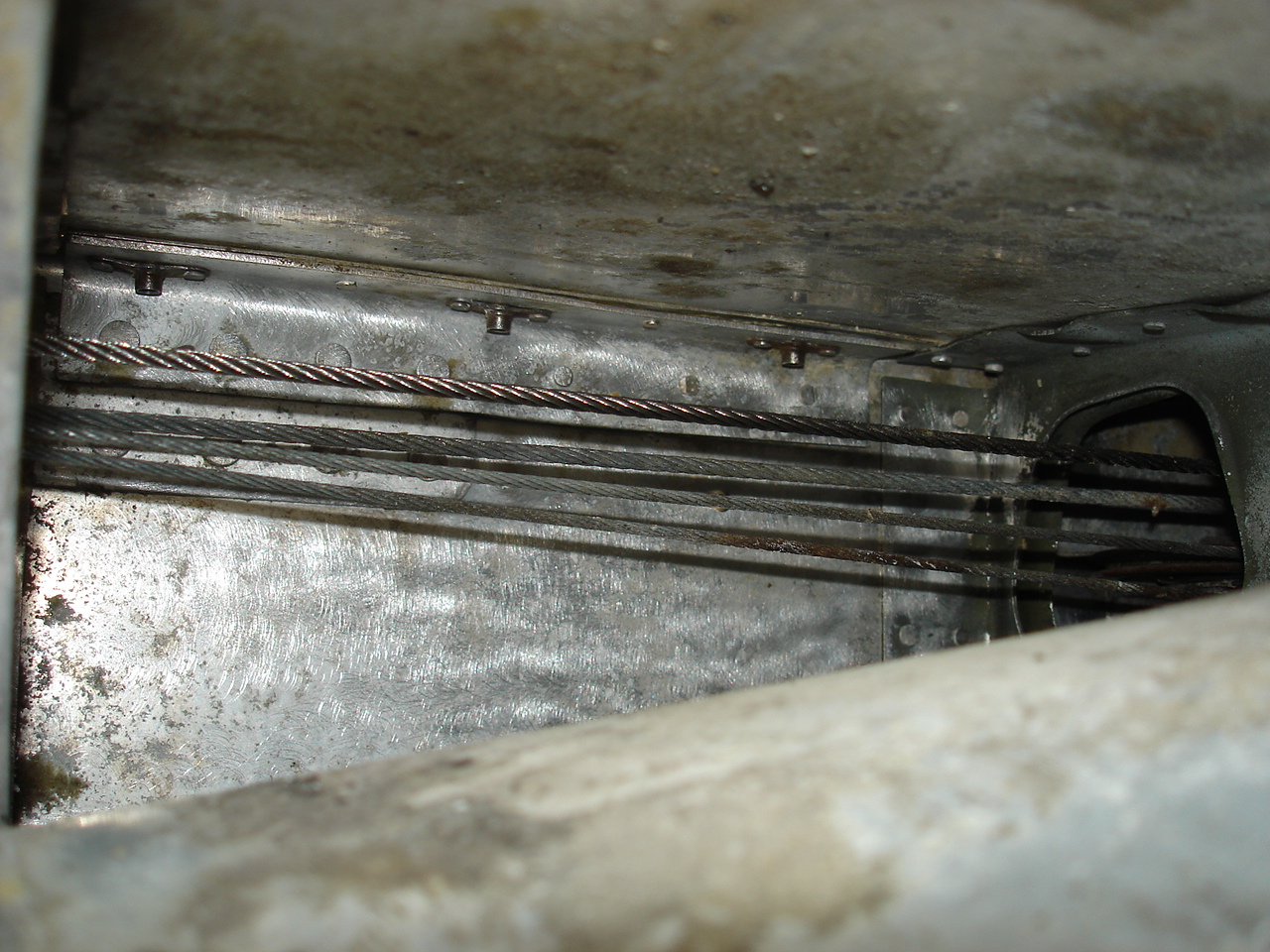
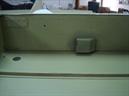
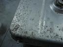
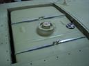
Just to back up one step ago, these photos show what I found when I took the tank covers off. The idea was to replace the rusty screws in the tank cover with new stainless after painting. What happened was this uncovered some nasty corrosion in the rear wing spars on both sides of the spar and in both wings. Thankfully, this was caught just in time. As you can see in the third photo, this has progressed to the point of missing rivet heads in the spar due to the corrosion. I had to remove some rivets in the flap cove skin around the inboard flap tracks in order to replace these rivets and clean and treat the corrosion on the backside of the spar. Also replaced some hardware-store "pop" rivets holding the flap tracks on.
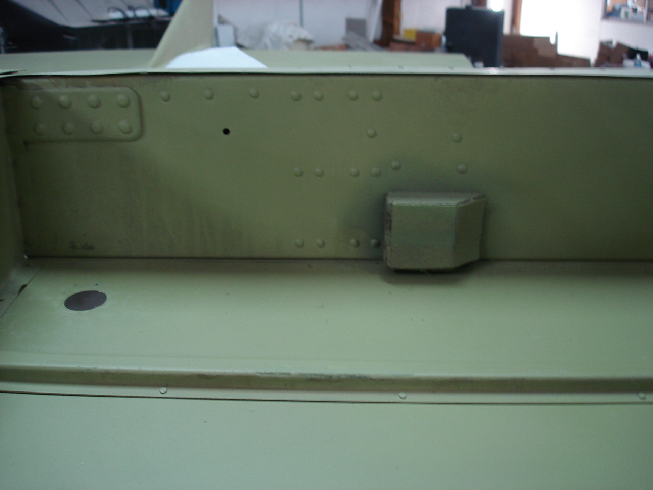
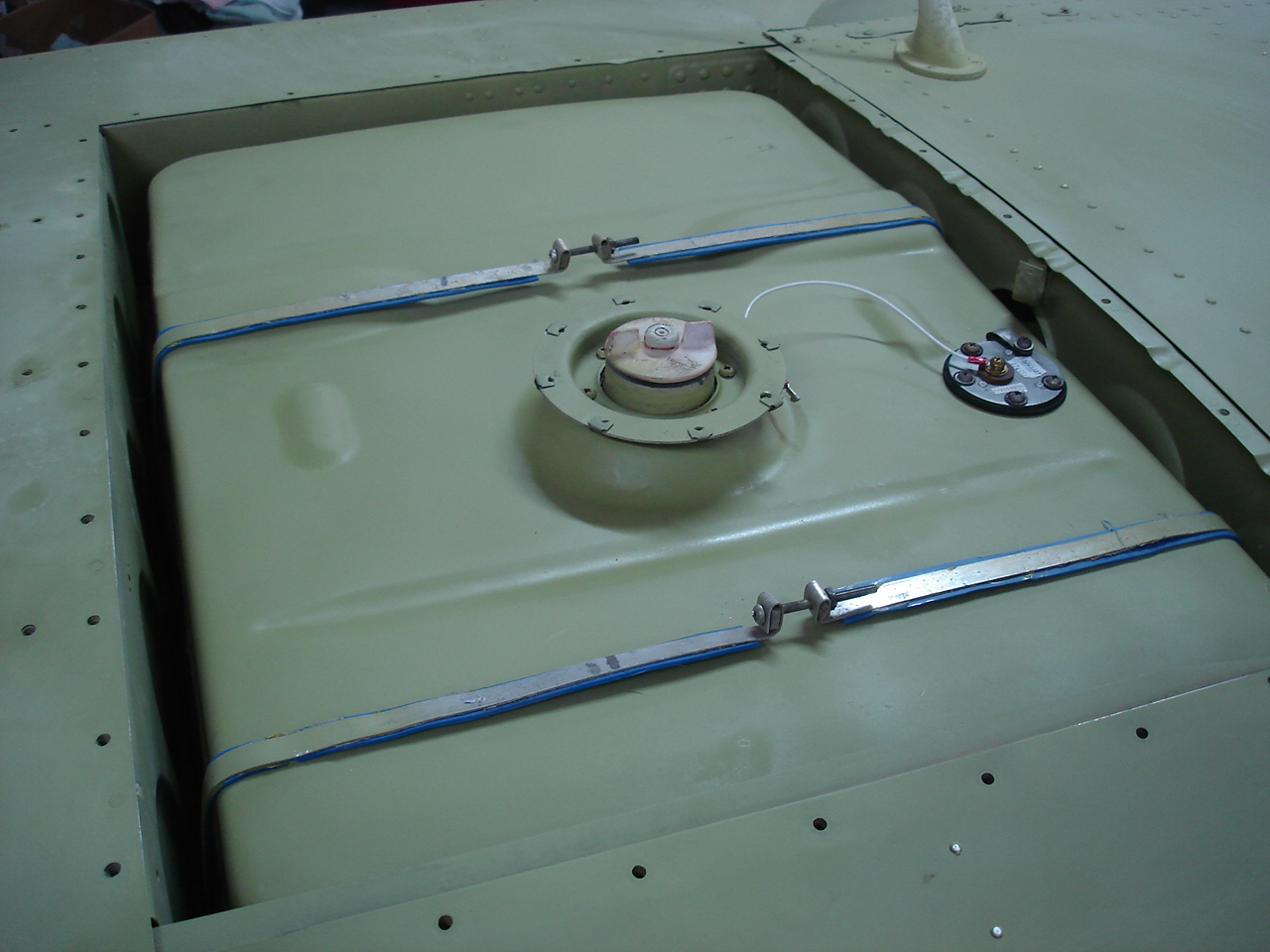
After careful cleaning, repairing, and treating the fuel tank bays are ready for the tanks to go back in. Installed some new chafe strips on the tank supports and also on the tank straps. The original chafe strips had gotten so brittle they wouldn't stay on and some were completely missing.
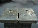

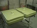
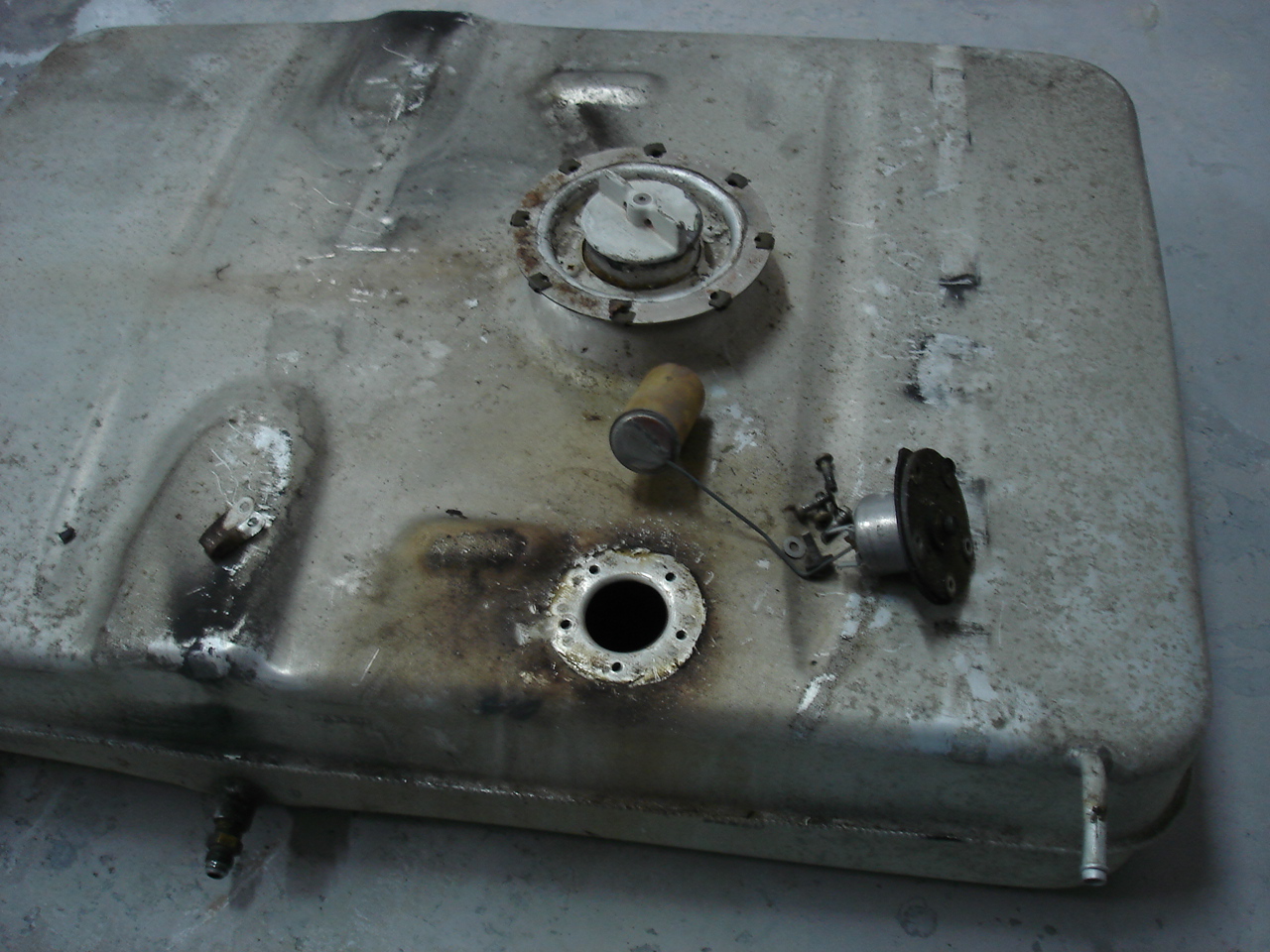
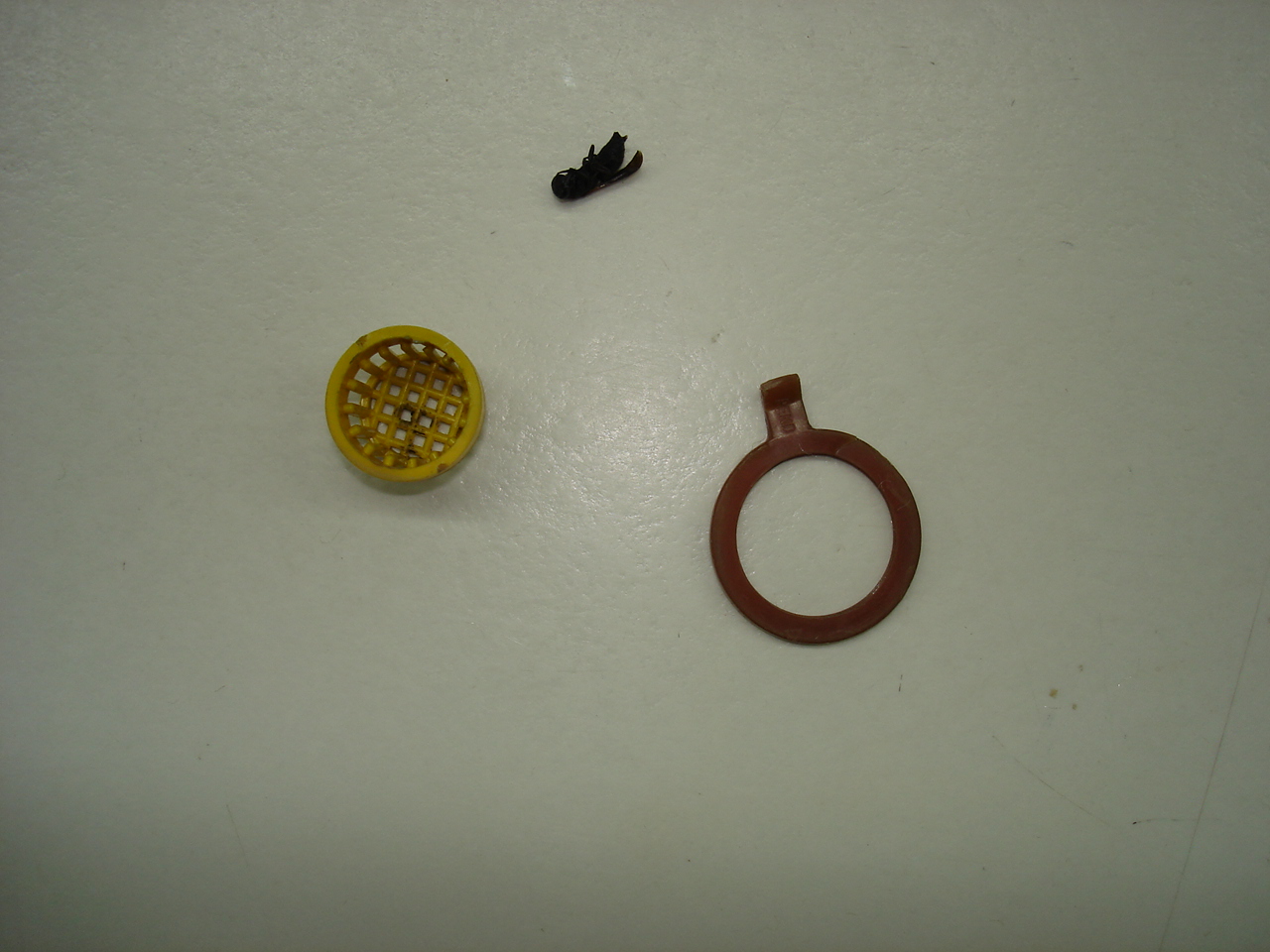
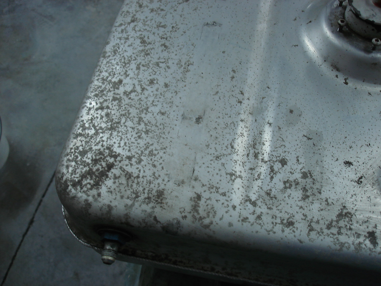
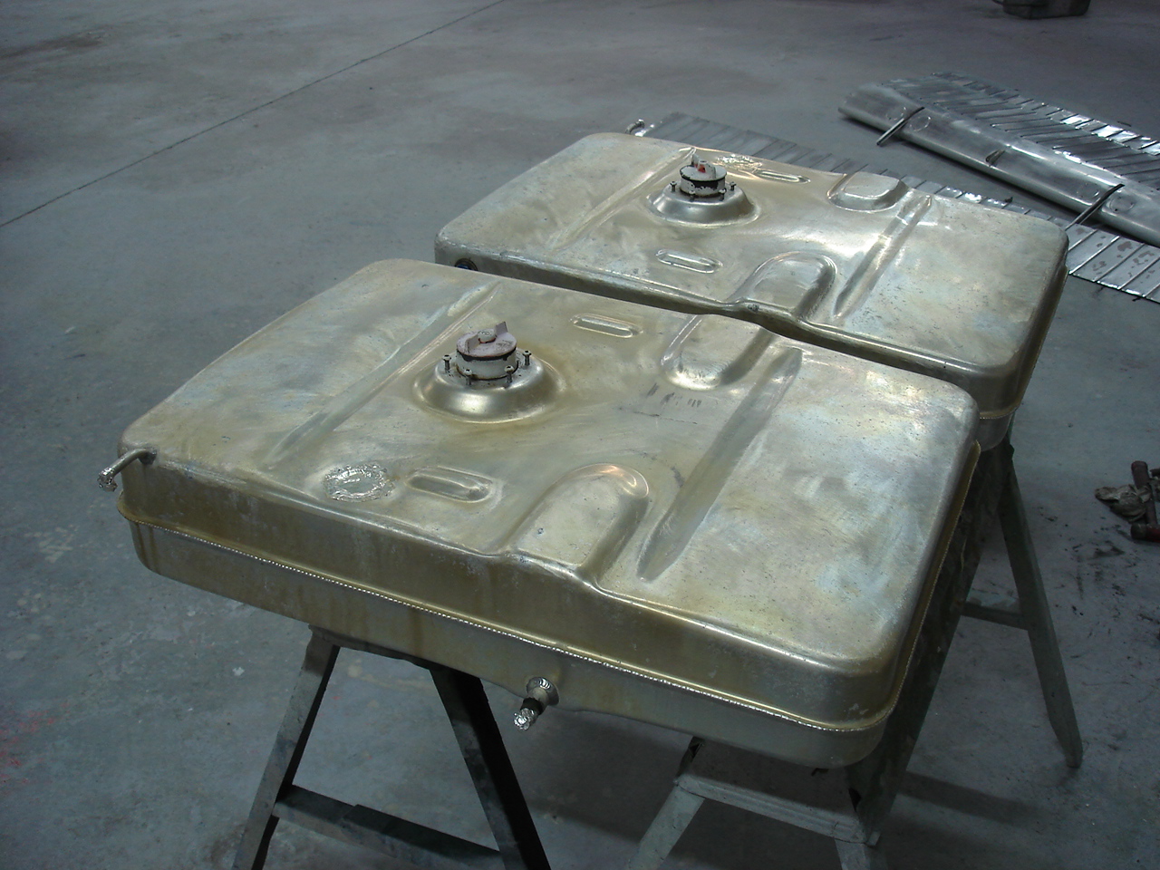
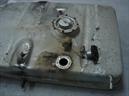
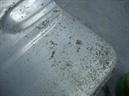
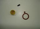
When I got the fuel tanks out, I noticed several things going on with them. The fuel sending units had been leaking at the gaskets, there was corrosion beginning to form on the tanks, and there were other spots of corrosion where the tank straps held the tanks down. This would prove to clean up very well, and I went ahead and acid etched and alodyned the tanks. They look so nice, I hate to do anything else. But, a trip to the paint booth will give it the best we can do so we come out with some epoxy chromated fuel tanks. Too bad Cessna never did this to begin with. I had both fuel sending units overhauled and I've got new gaskets and hoses to re-install the tanks. To top it off, I've got new flush mounted fuel quick drains from Cessna to replace the mix-matched ones we had. I'll leave the old fuel caps on for now until I'm finished painting. We'll have new vented caps on it when we finish. While cleaning the tanks, I heard something rattling around inside. Fished it out and it looks like somebody probably tried to put gas in out of a can (probably car gas !). Anyway, looks like they dropped part of the nozzle down inside the tank. Got some bugs to go with it, too. Nice. Hard to believe there's this much work just to the fuel tanks.
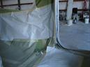
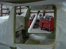
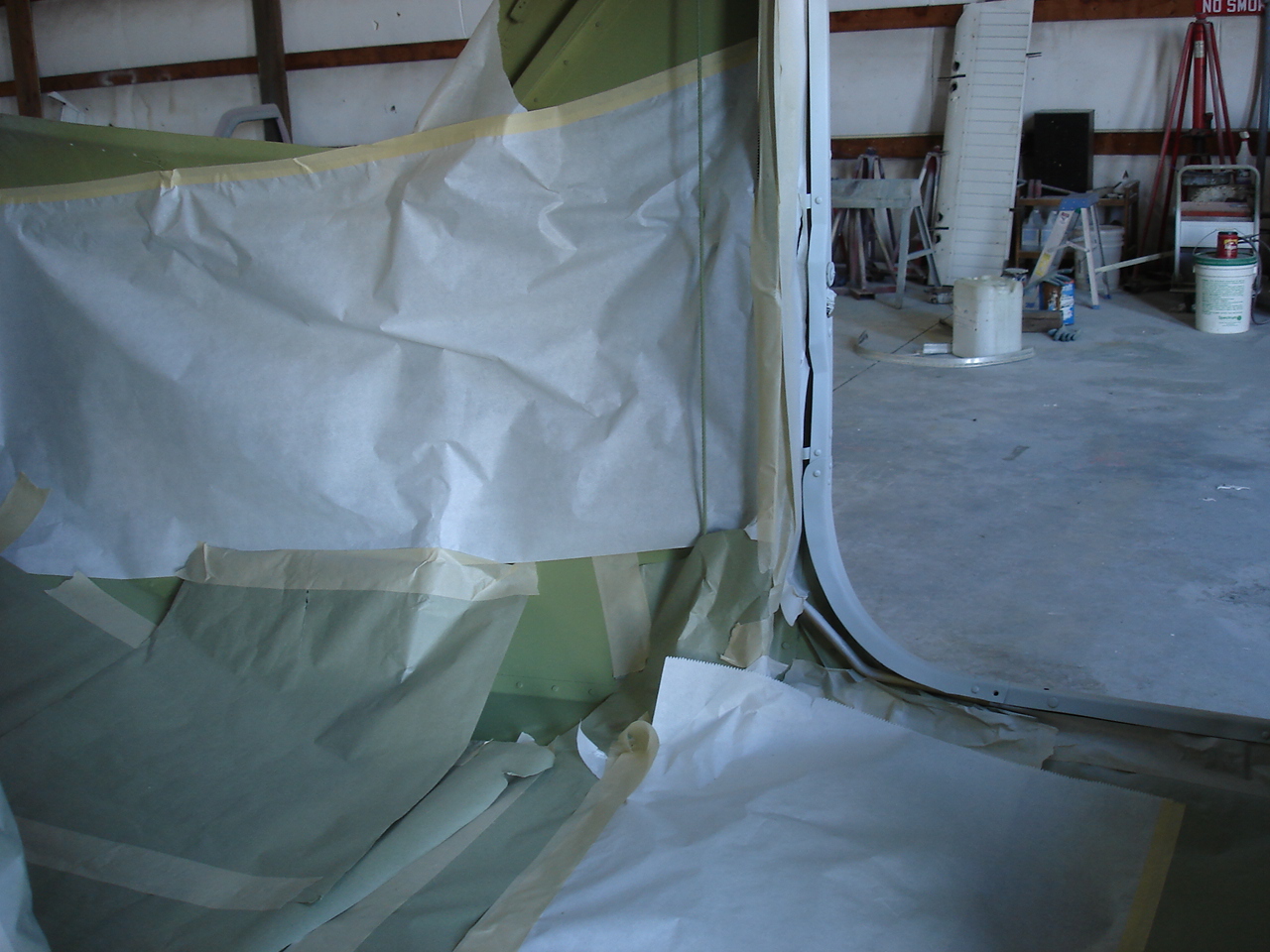
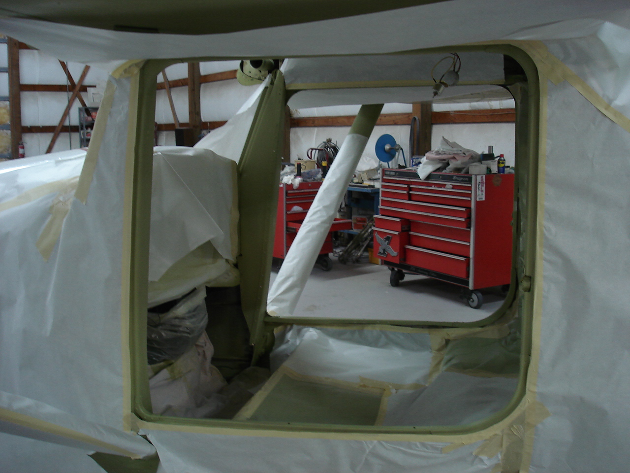
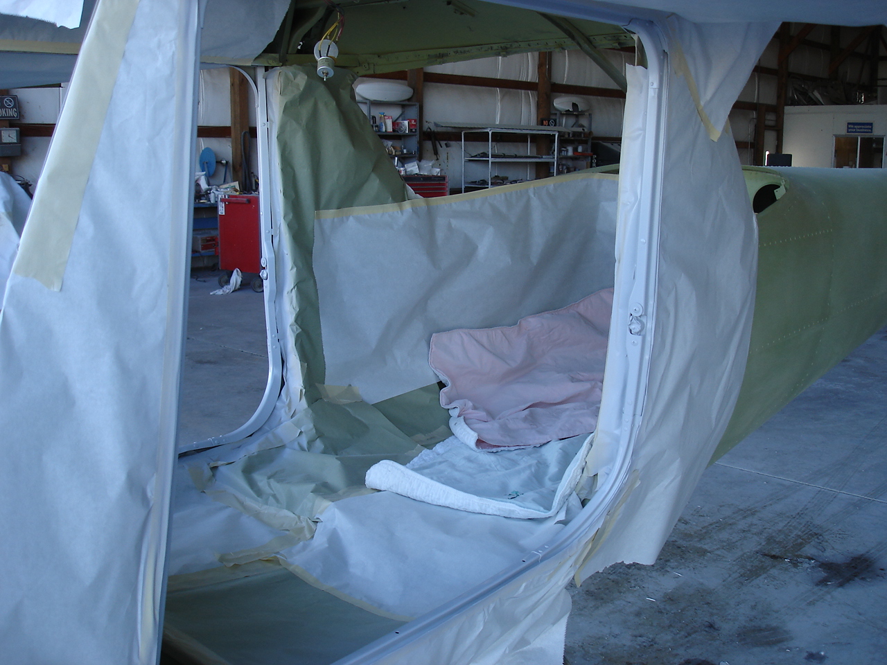
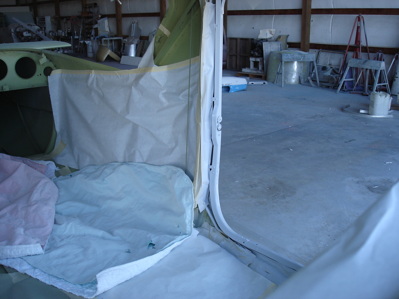
Here we start to jamb it out. The Jet-Flex interior finish requires a special primer to go on before the Jet-Flex color. This will give us a nice look since the primer will allow the metal pieces of the interior to be the same color as the plastics. This should give us a nice, even look to our project. Lots of masking and detail work here.
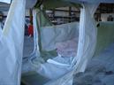
This is just a quick shot as we put part of the sound-proofing in. This is high density foam insulation that will help absorb the sound and vibrations from the airframe. Its extremely light weight, so it doesn't weigh hardly anything, but it looks heavy. I follow this with a fiberglass "sealed bag" insulation for the large voids and draft areas.
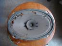
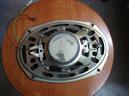

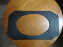
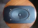
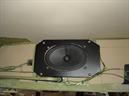
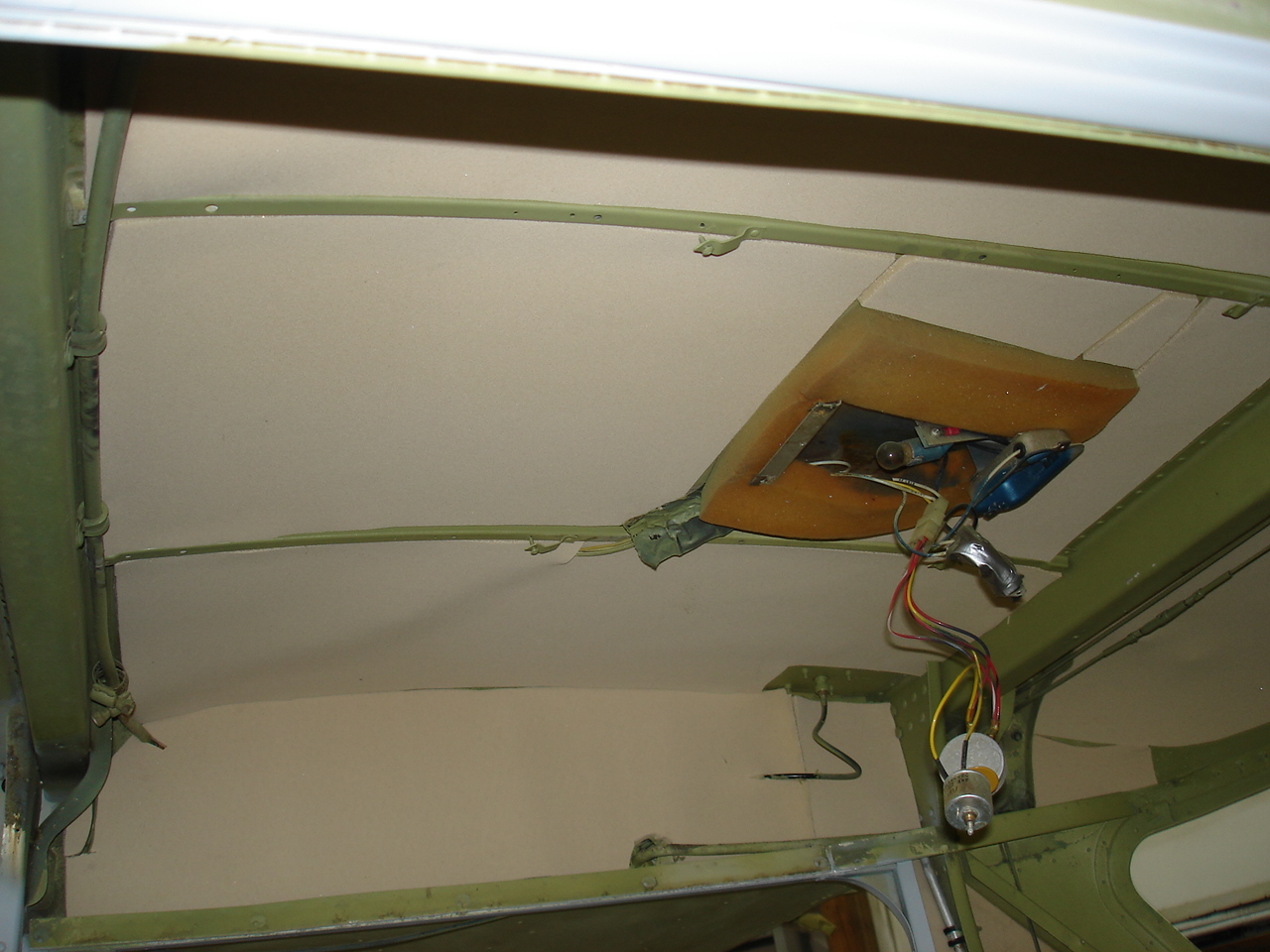
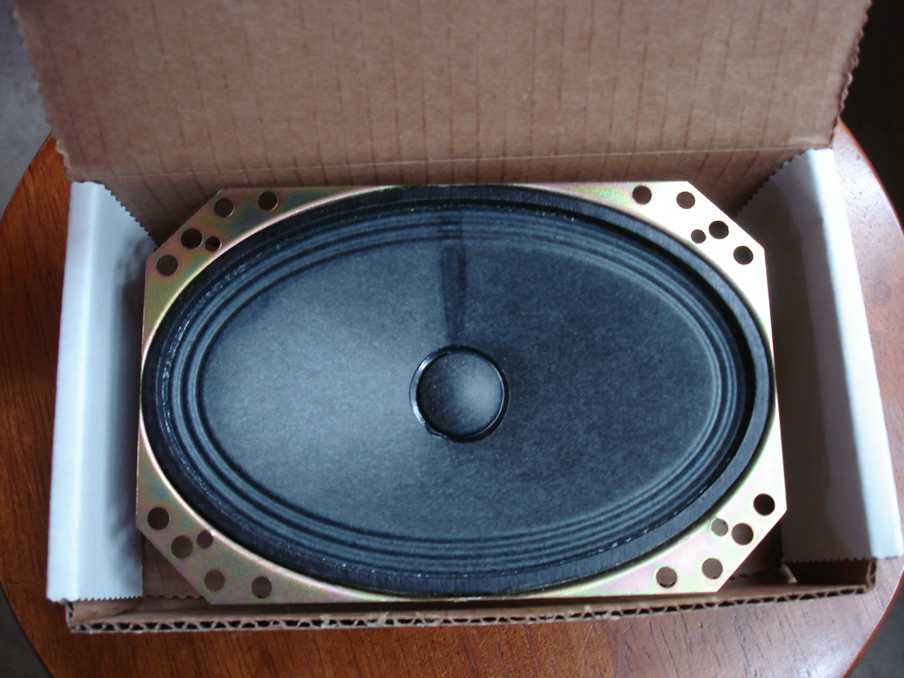
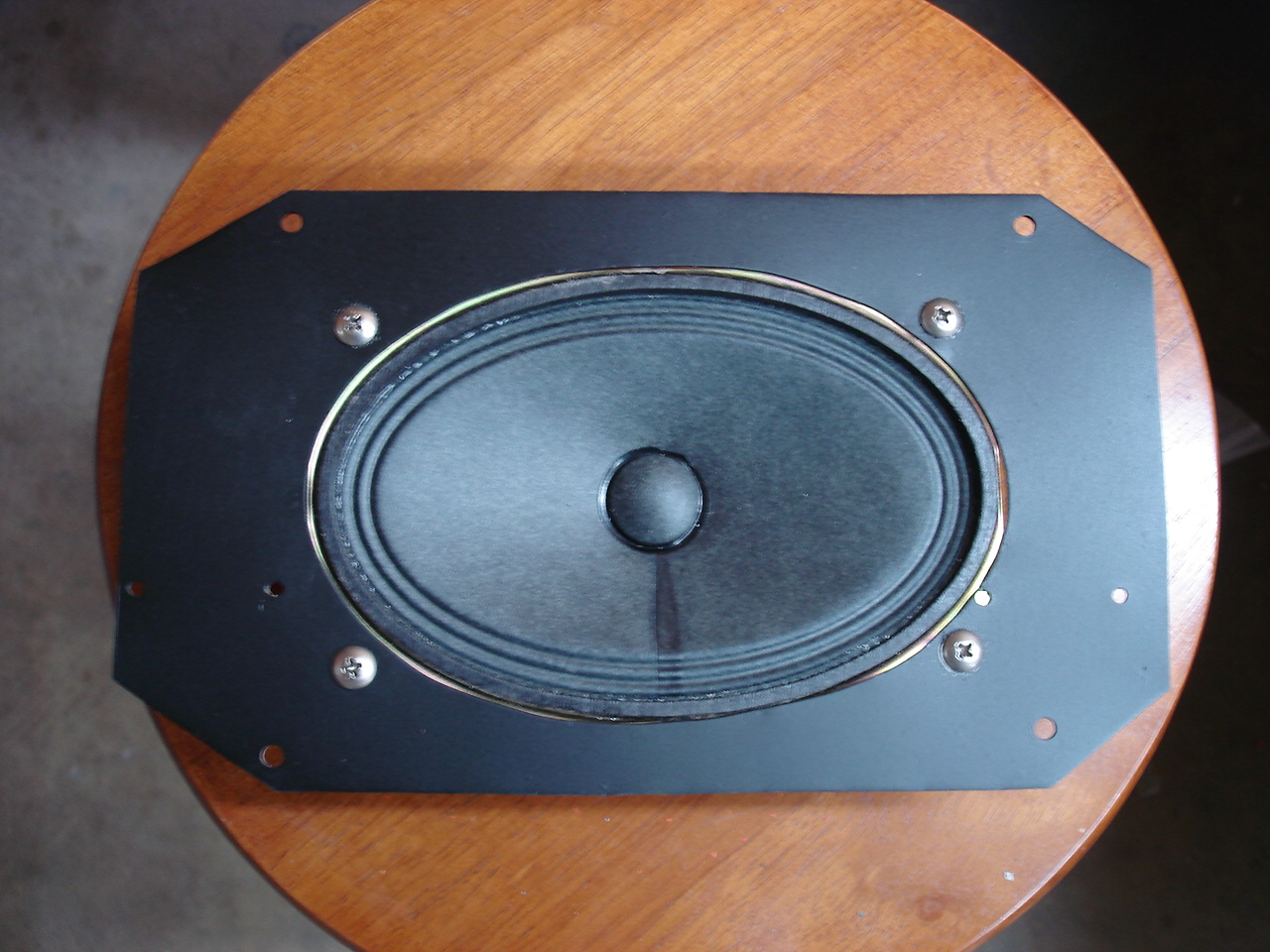
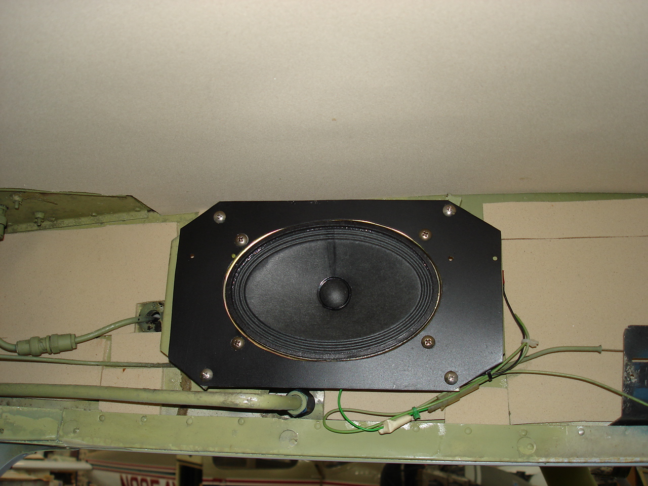
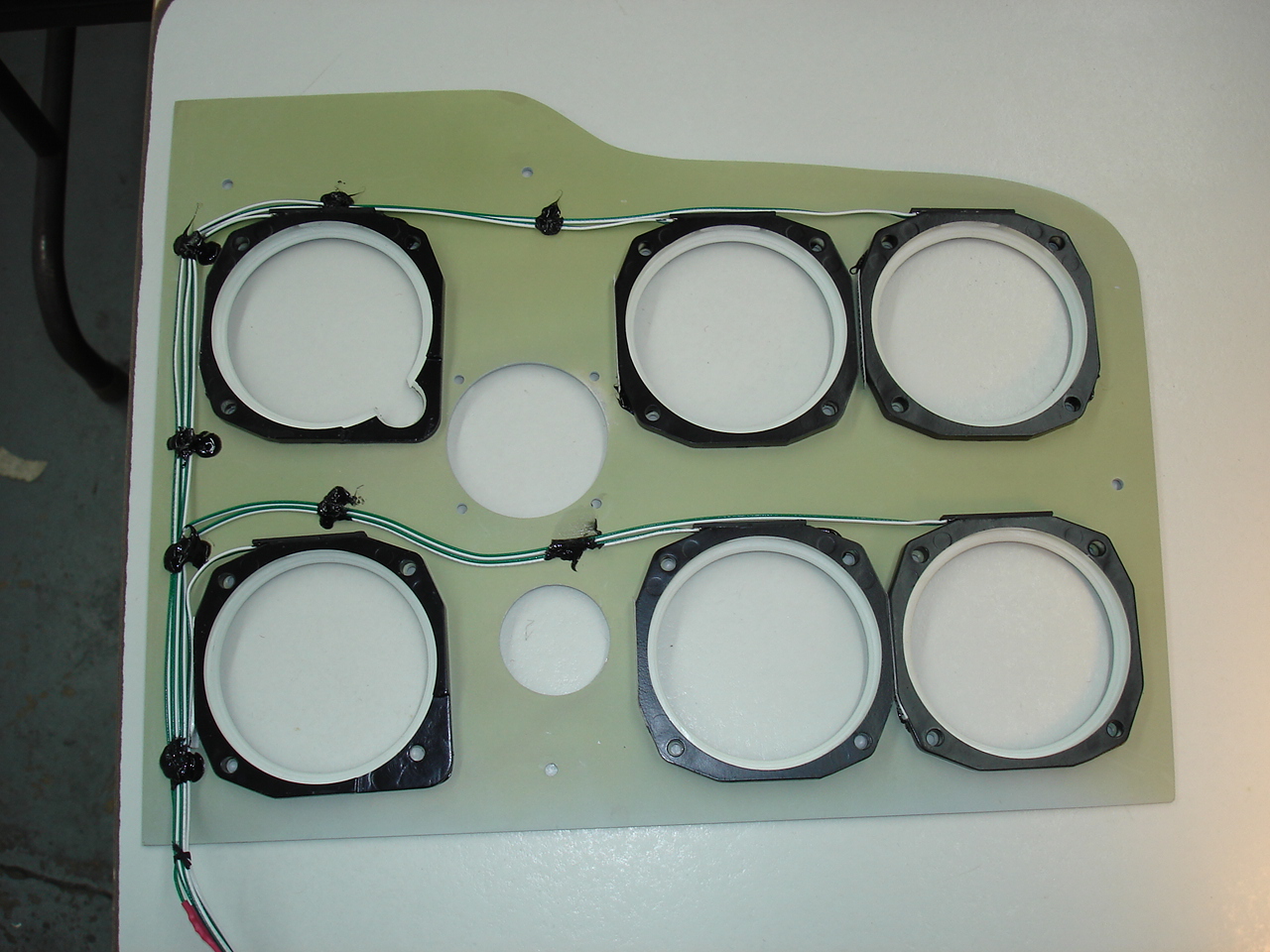
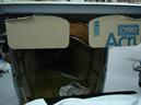
Looks like the rats had some fun with the radio speaker. I knew there was something not right with it anyway because it jutted out into the headliner. When I got the headliner out, I noticed that while the speaker was the same diameter as the original 6X9, it was way too thick and was sitting on the fuselage end rib. When I got it out, I found out why. Realistic brand from Radio Shack. Since the 6X9s for aircraft applications are nearly impossible to find, we'll go with an oval quam type speaker. This is smaller than the original, so I made an adapter plate. Fits right in the original mounting bracket now. I made sure I put the sound proofing in behind it too before I put it on the bracket.
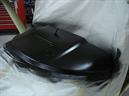

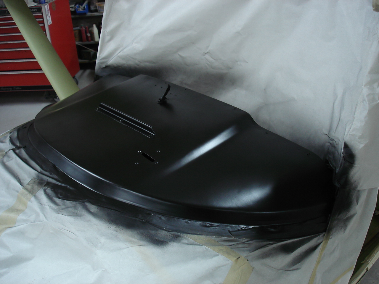
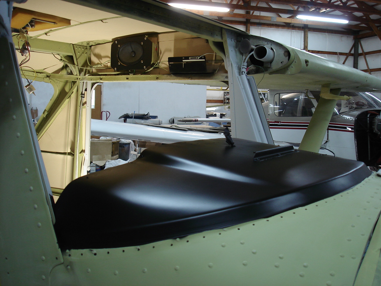
Next in line for finish work is the glareshield. Lots of taping and masking here because I want a low gloss black finish. I'm embarrassed to say that it took me three attempts at this before I got the finish that I wanted. Came out nice and smooth, though, with the elusive low-gloss "sheen". Should look really great with our black leather eyebrow.
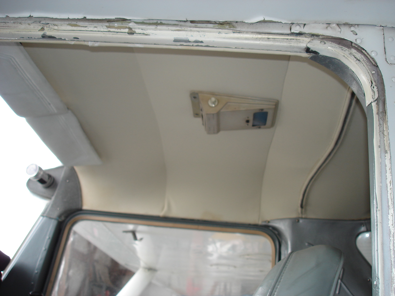
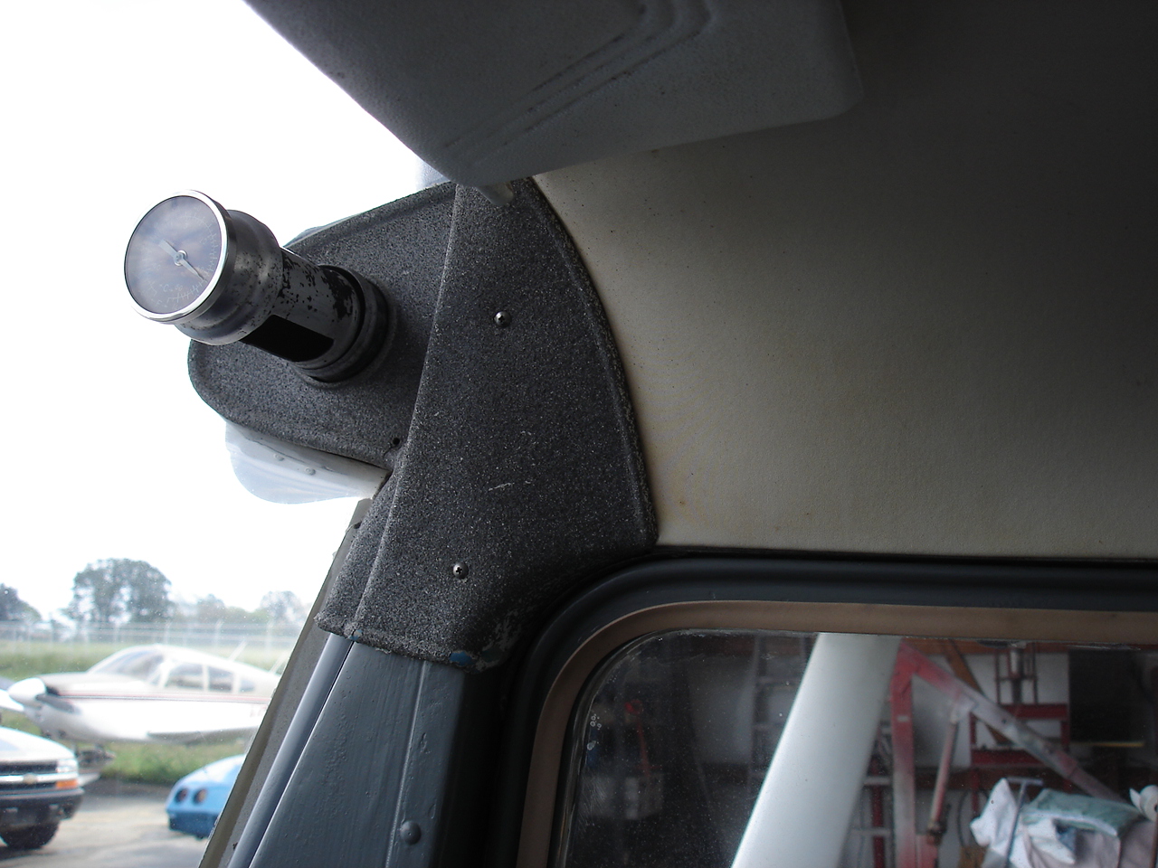
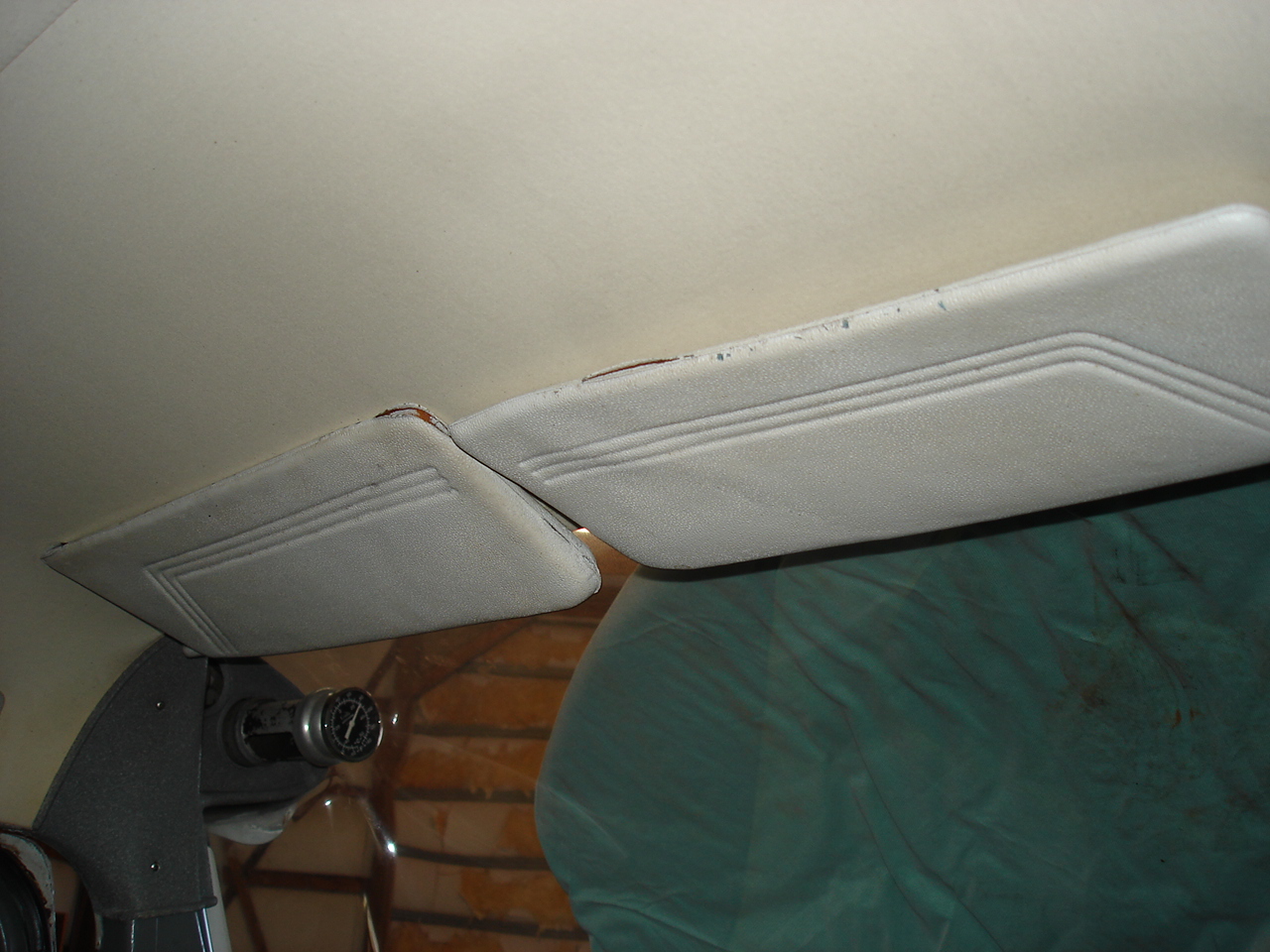
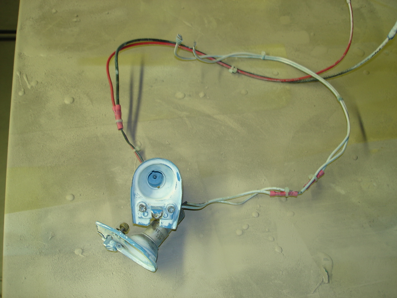
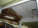
O.k., I had a brain storm, so I hope this works out. I decided that the flap indicator has absolutely no lighting at all at night. Especially since this model has the indicator over the top of the pilot's door, it'll be especially hard to see. So, since I painted the indicator and base, I thought I'd add a 4" light bar to it. This needs to be done now before the headliner and windshield is installed so I can get the wires routed properly around the door post. This should provide us a nice glow to the indicator marker from behind the flap indicator cover. The light itself will be totally invisible from the outside of the headliner, but should work well here. It'll be on the panel light dimmer so that'll be nice too.
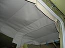
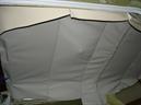
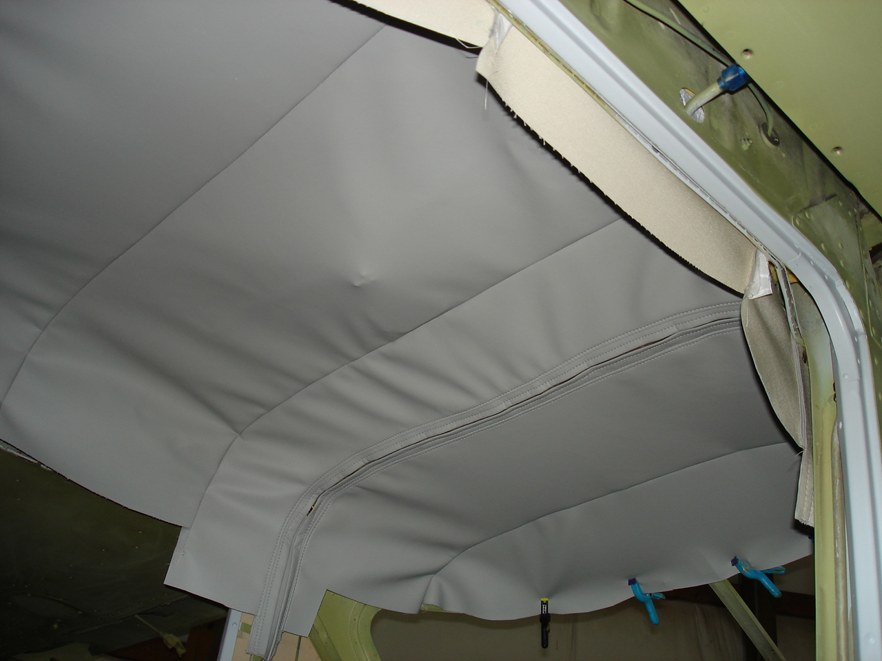
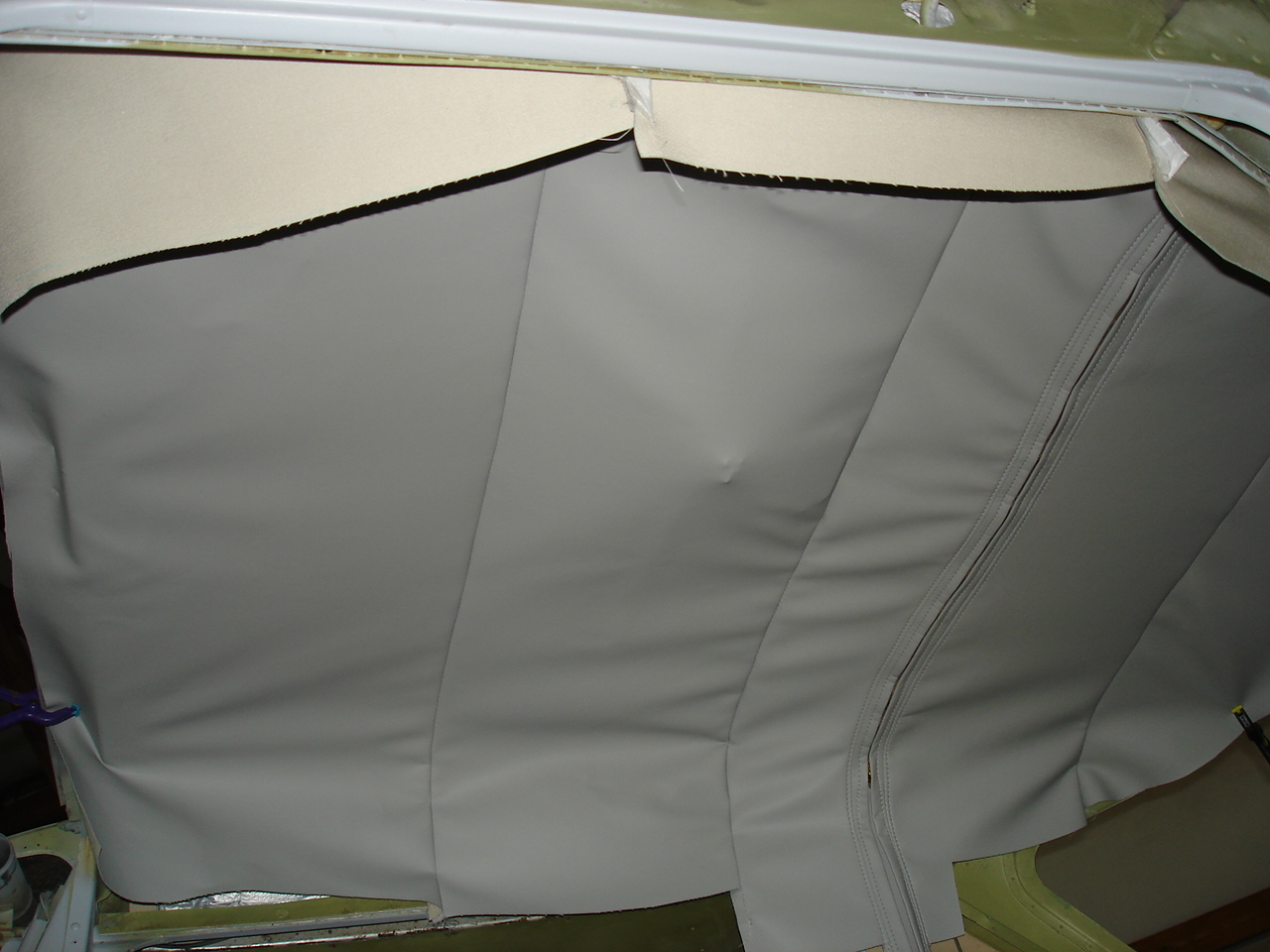
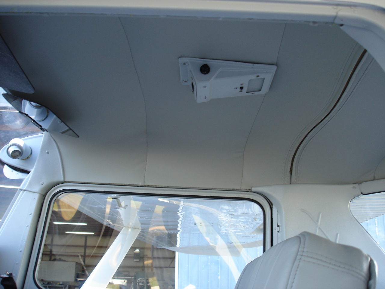
Lots of other fabrication work has been going on with this and now we are beginning to see some results for all our efforts. The headliner is now fabricated from an ultra-leather type material. Since we're doing a grey themed interior, it's whistler grey. Here we see the initial fit after installation of the bows. The soft headliners in the 150s must have a listing sewn into the backside of the headliner to accommodate the metal bows which give it the shape. The headliner is then worked by hand to stretch it tight to make a smooth, uniform finish. More photos of this process hopefully tomorrow if time permits.
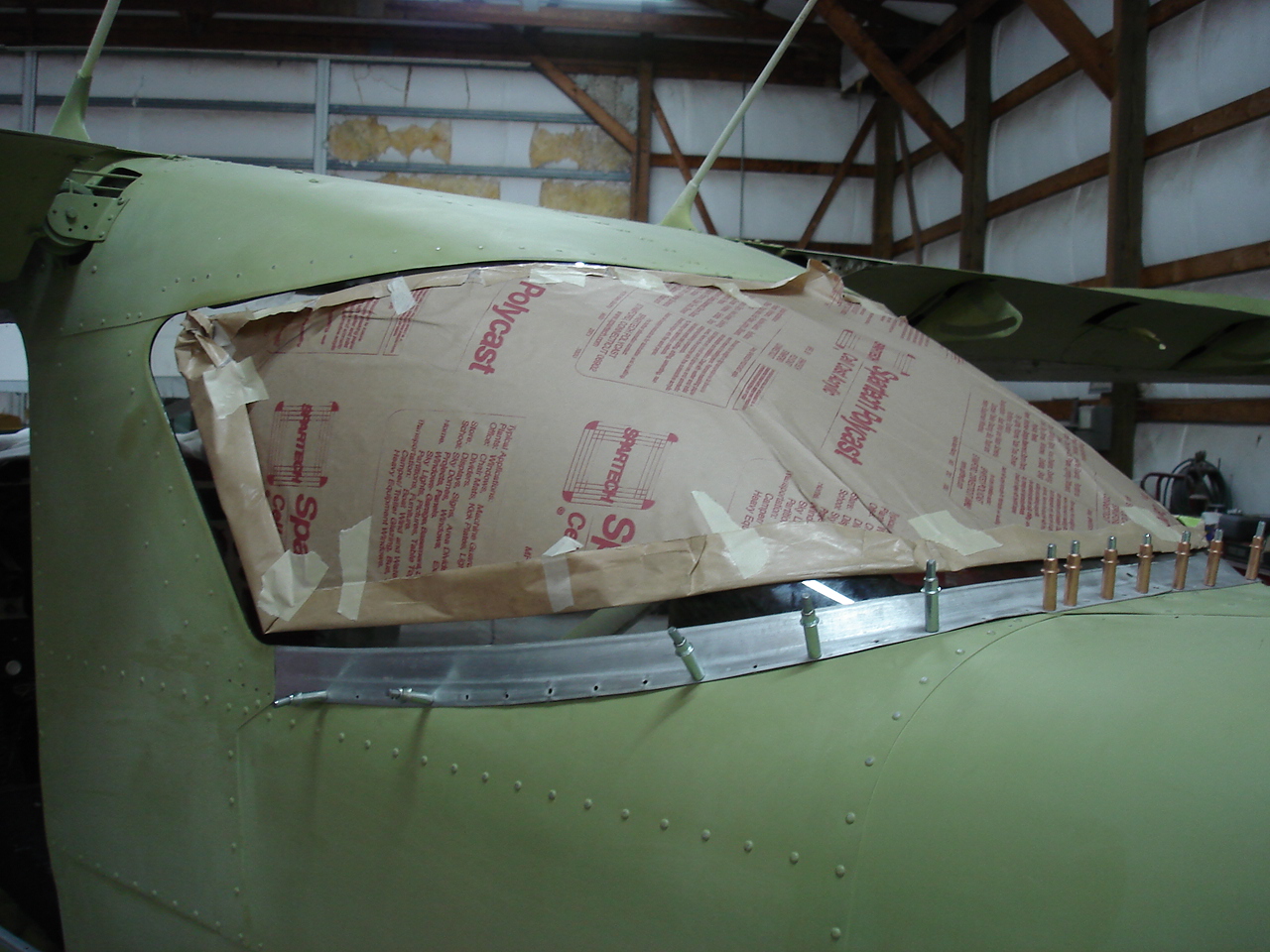
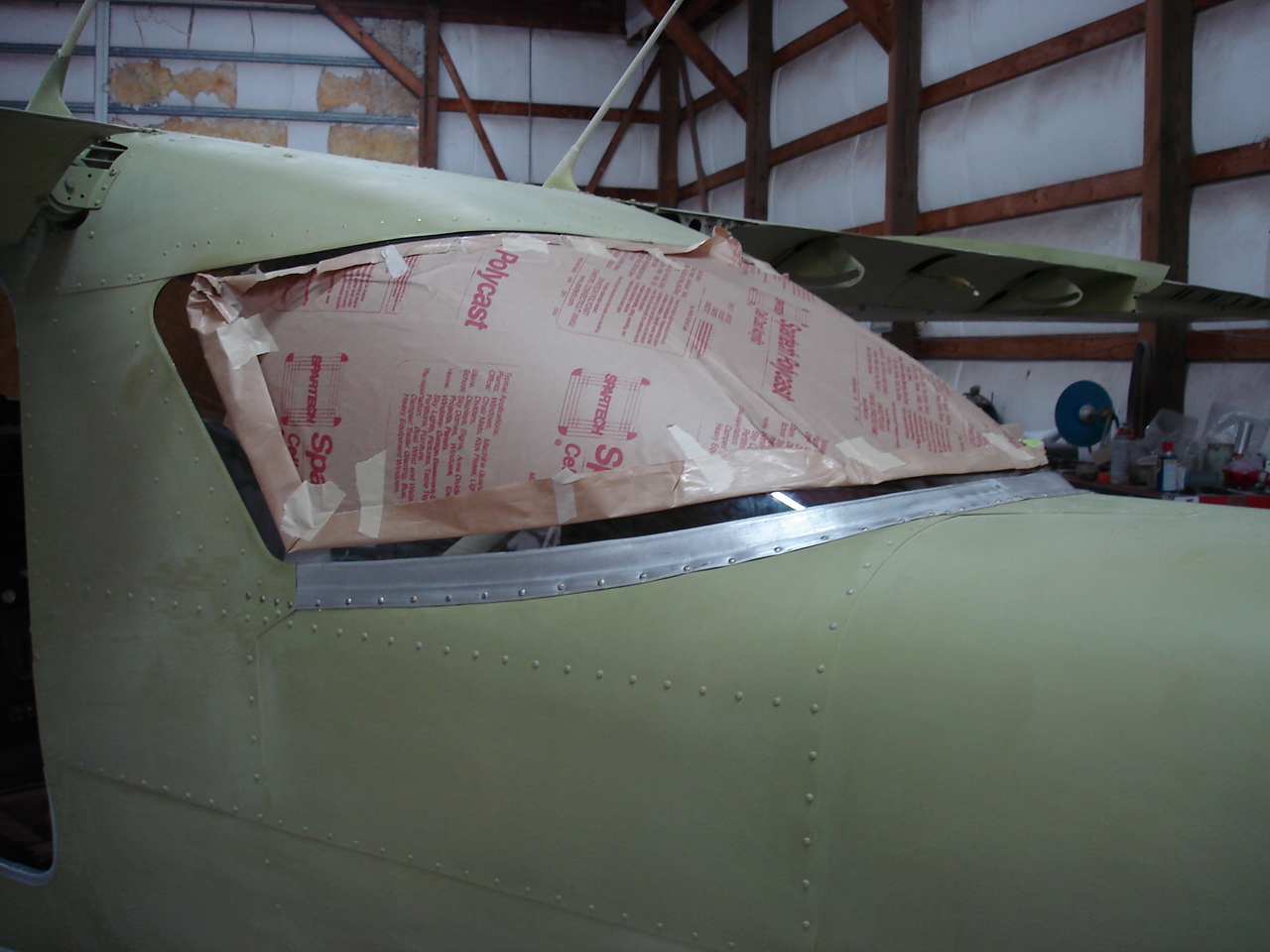
Once the headliner is stretched tight and fastened to stay along the edges, we can now start putting more finished stuff back on. The trim pieces for the forward cabin should be painted and installed with the new tinted sun visors prior to installing the windshield. Also, its much easier to run wiring down the door posts to accommodate the new strobes at this time. After all this trim & whatnot is installed, we can now put the rear window and windshield in place. These are prepped and installed using new felt gaskets throughout and are set in place. To make an extreme understatement, these are "push fit". In other words, an exact fit for where they go this and not a fraction more. Rivets are then used to fasten the window straps down just like the original manufacturer process. Lots of fun here, but the end result is what makes the difference. Nothing like new tinted glass in an airplane.
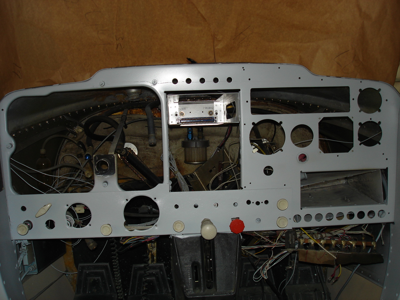
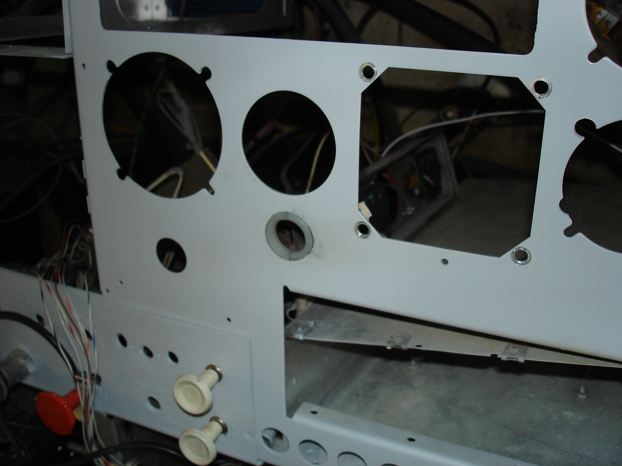
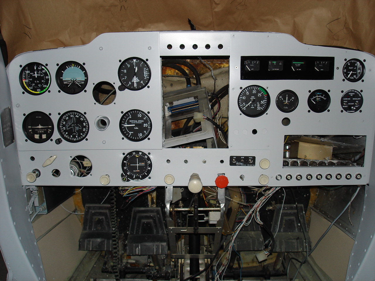
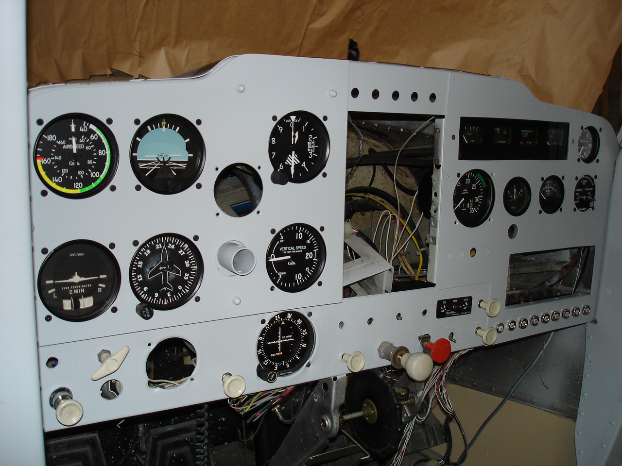
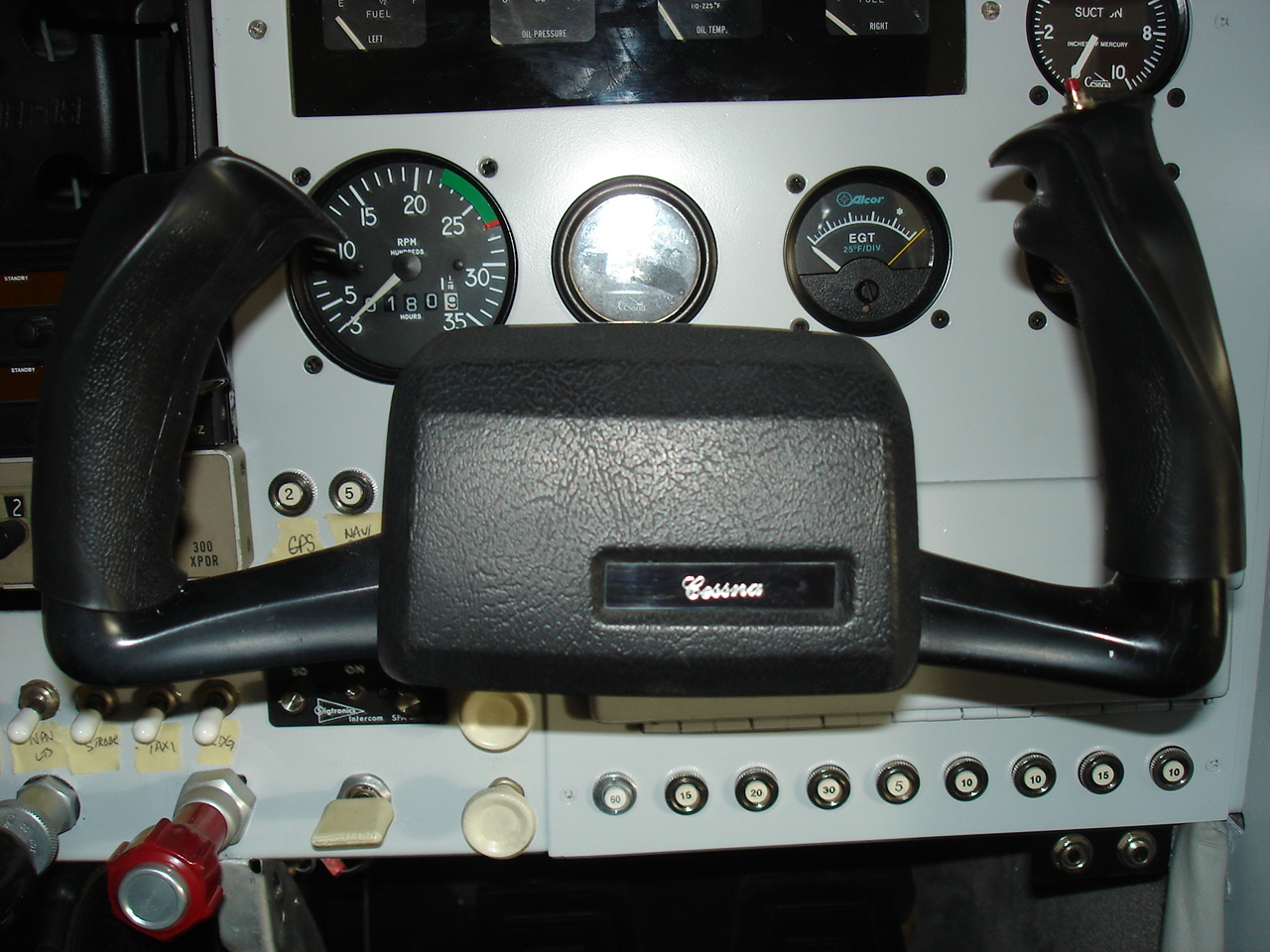
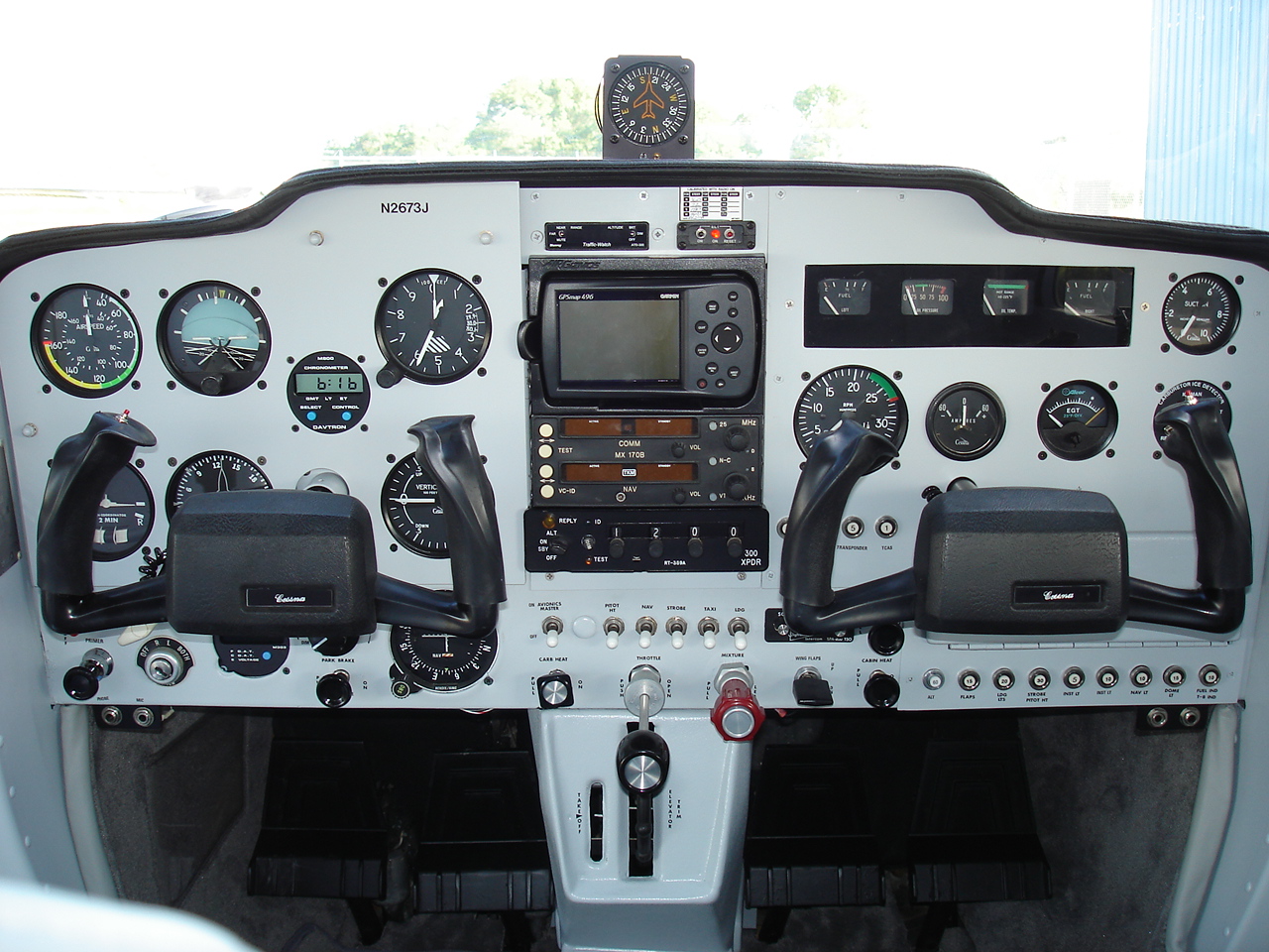
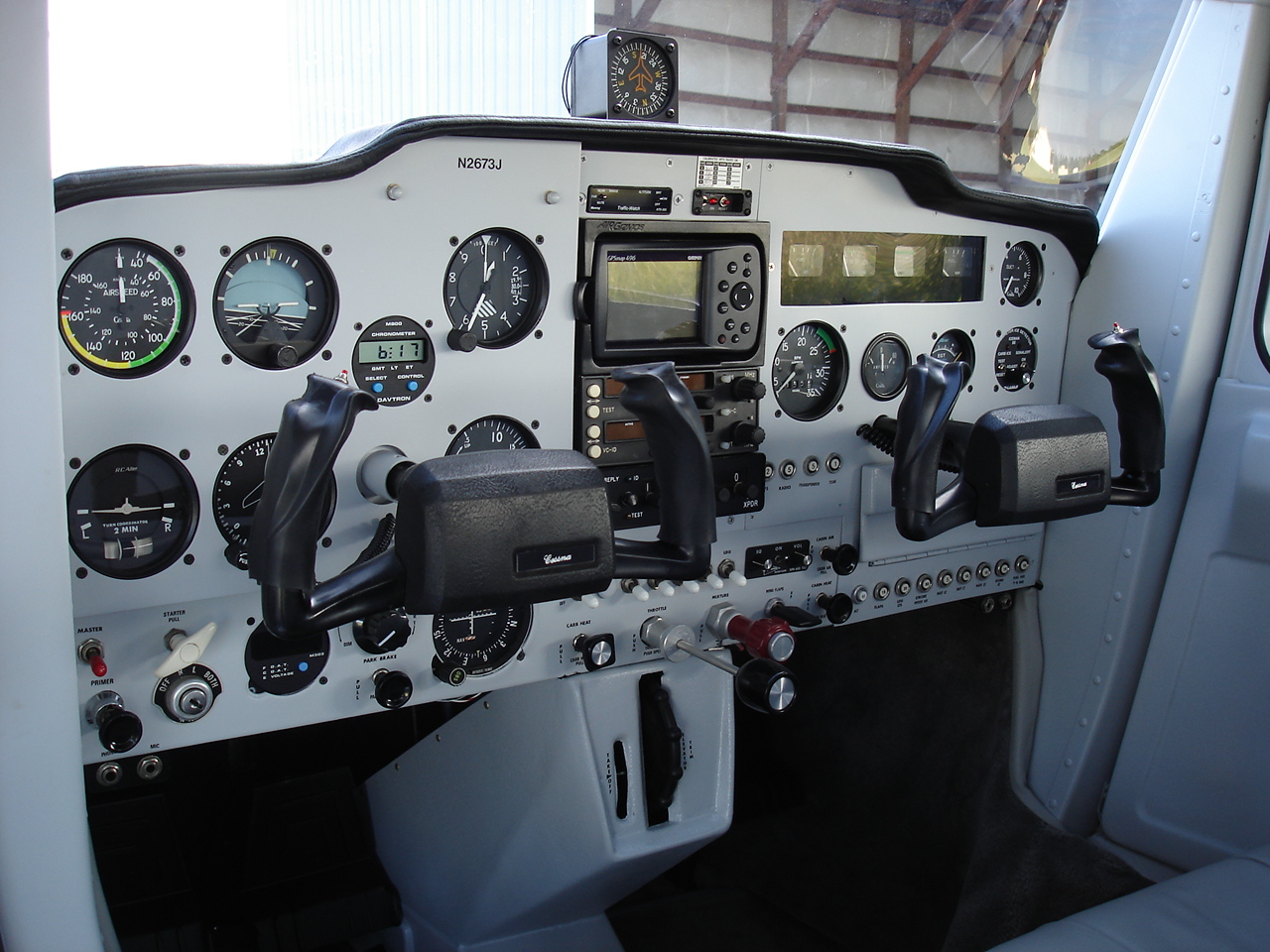
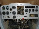
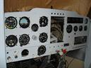
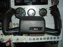
O.k., here I start the panel phase of our project. Just a couple of pictures at first as a reminder of what I started with. The plastic overlays had been painted over and over and were somewhat butchered. The last pic here shows the basic structure after the plastic and the eyebrow were removed.
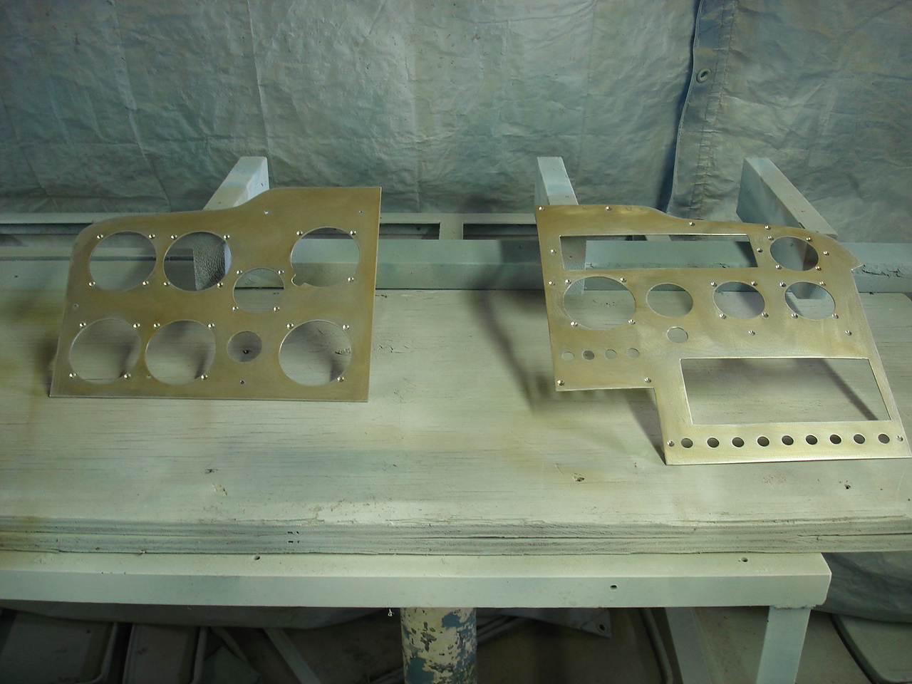
Here I pick up the photos after the initial disassembly and the fabrication is underway. The first step is the fabricating of a mockup panel to give me the layout that I want and to set the size of each section that I make. Next, the basic panel is cut and in the first shot we see the resulting blank canvas. The second shot shows the initial layout after the first cuts and the edges have all been filed and set where I want them. Raw metal fab just the way I like it ! Lots of cutting, drilling, filing, fitting and more of the same until I get what I want. The final shot shows the panel after the instrument mounting holes have been drilled. I like flush screws in my panels, so some extra time and effort here will let me have those smooth, flat screws holding everything in. Should look really rich. Next, I go to prep and paint for it !
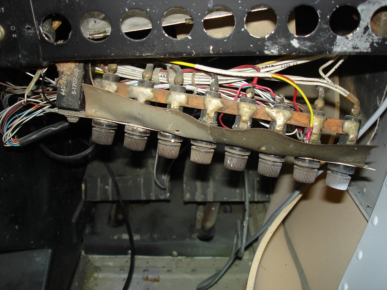
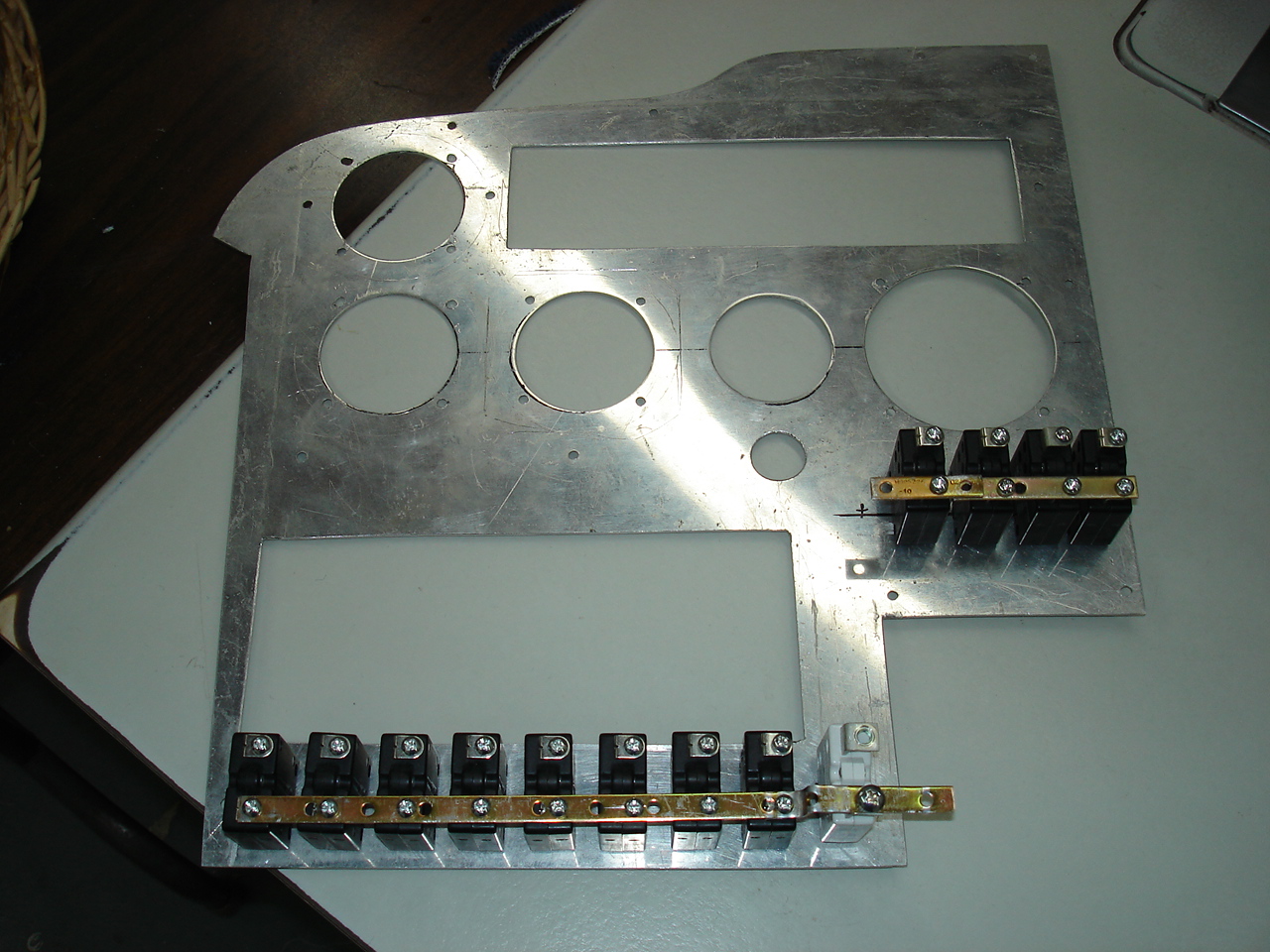
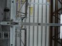
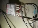
Well, one more thing before prep and paint the panel. I wanted to get the new bus bar fitted before I did the final paint. Here, you see a close up of the the old original fuse holders all nasty and corroded. What I'm doing in the second photo is a mock up of a new bus bar and circuit breaker installation. This is all new mil-spec hardware. What I had to do was fit each breaker to the bus so that they'll all fit the final panel once it is installed in the airplane. Also, while I was at it, I thought it'd be a good idea to add an avionics bus bar so I can put an avionics master switch in. Might as well as long as I've got all this out. Also, I added a couple of extra breakers on the bus to maybe help out with future equipment installations should that ever be desired. Now maybe I can go ahead and paint the panel. Can't wait to see how it turns out.
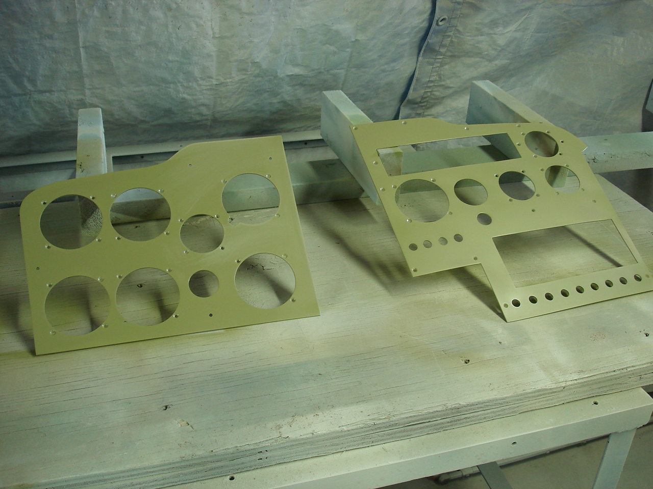
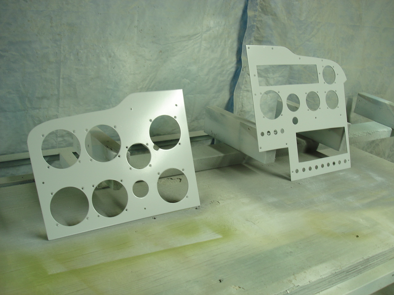
First, I prep and paint the airframe base. Next, the Jet-Flex process starts using the same process and colors as I did on the door posts, etc. Etch, alodyne, epoxy corrosion prime, Jet-Flex poly prime, then Jet-Flex low gloss finish. A long painting process for a just a panel, but I love the silky smooth finish it gives it. Nothing else I've ever used equals it.
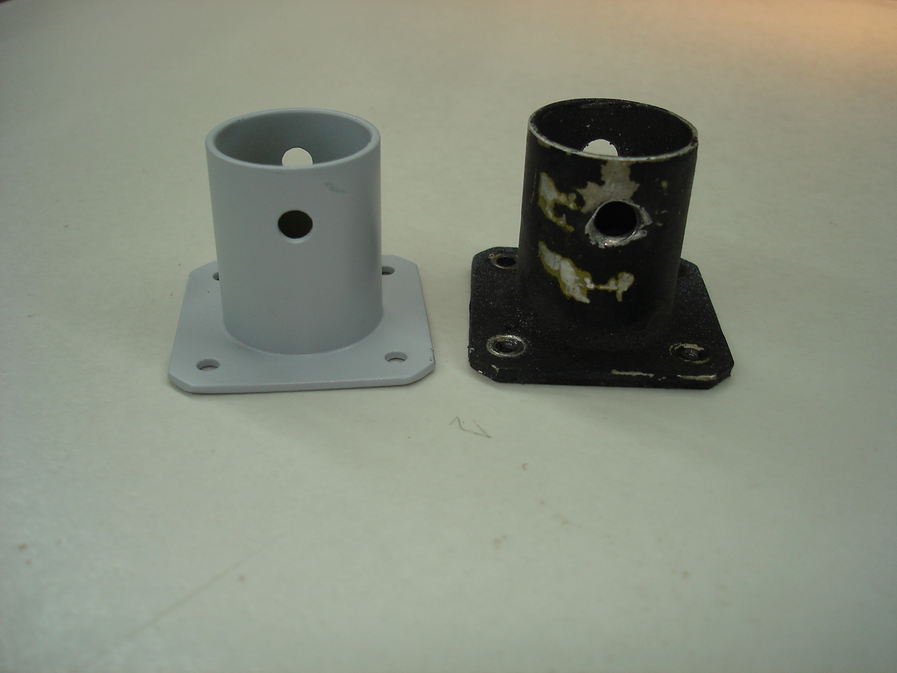
New nylon yoke guide bushings from Cessna are now installed into the airframe. The old ones were worn and tattered. Now's the best time to do it. The yoke guide on the left was elongated pretty bad where lock pin engages as show in the second photo. I painted the new one from Cessna to match the panel. Next comes the instrument bezel lights. These are installed on the backside of our panel to fit between the instrument glass and the panel. Each light is wired in drop in succession with the rest in preparation to go to the dimmer switch. Fastening the wiring to the backside of the panel makes a clean no fuss install.
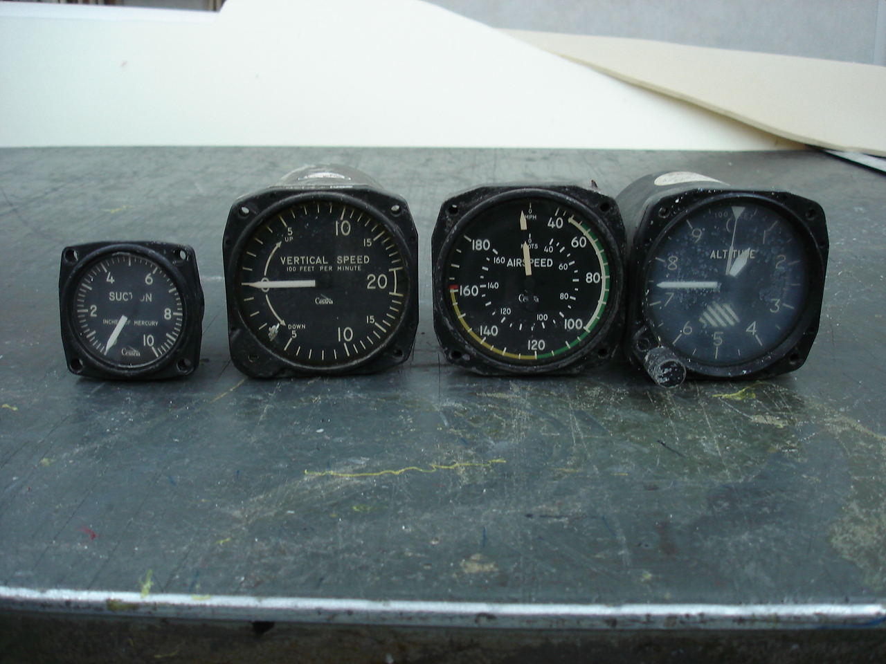
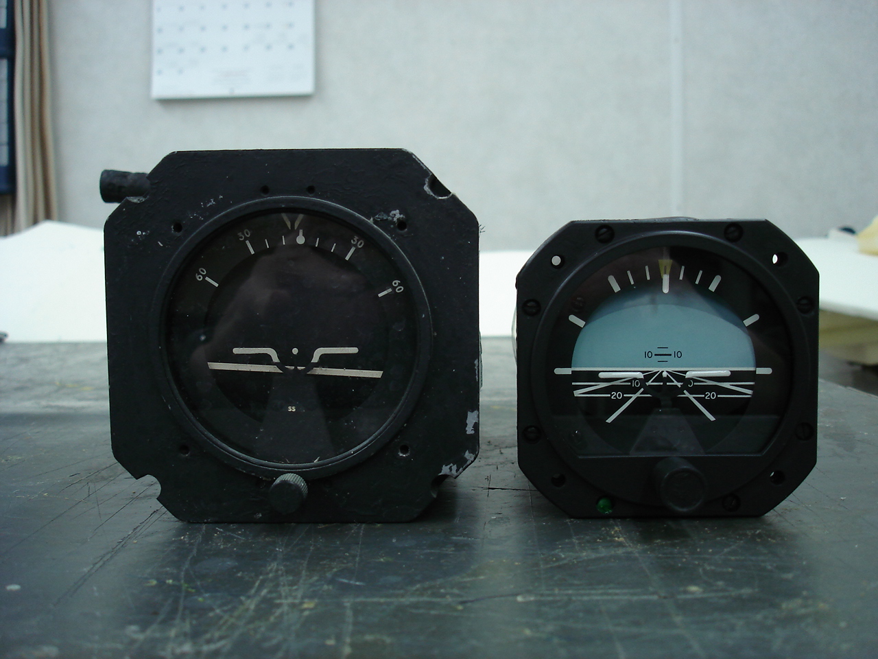
Newly overhauled instruments are now ready to go into the new panel. In the photos to the left, you see the original instruments looking pretty crusty. The photos to the right show the same instruments after overhaul featuring new dials. The original horizon is replaced with a later model unit newly overhauled.


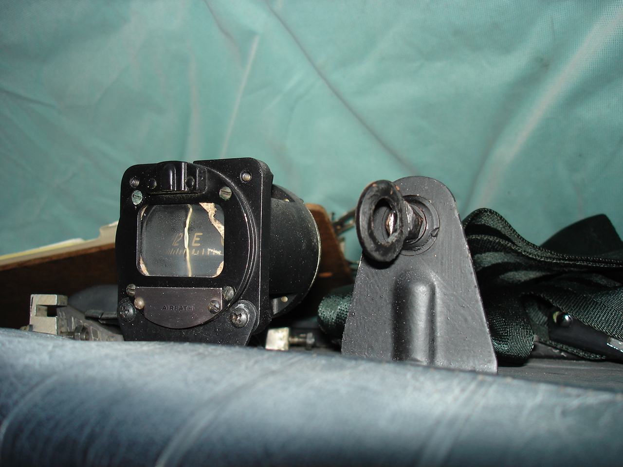
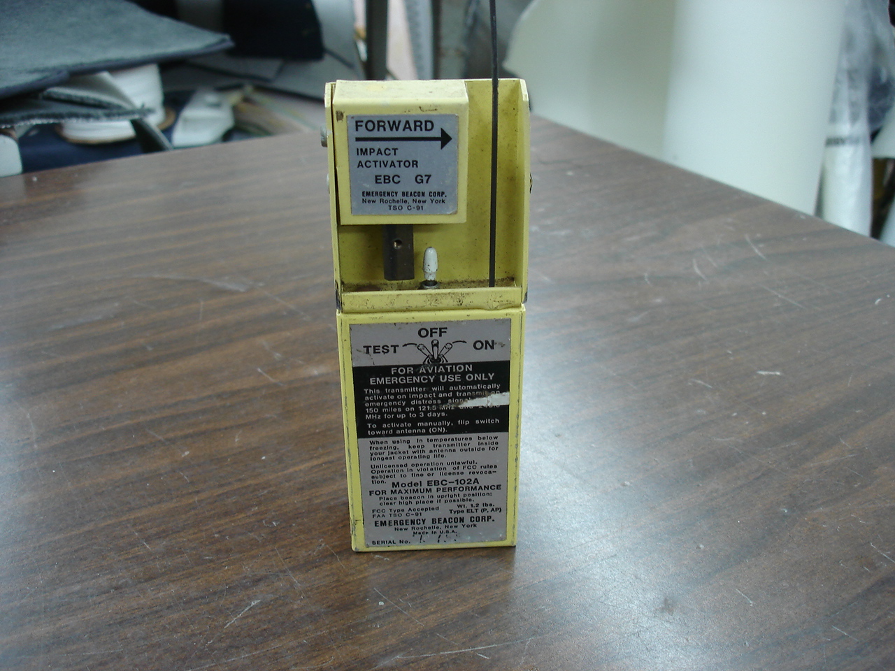
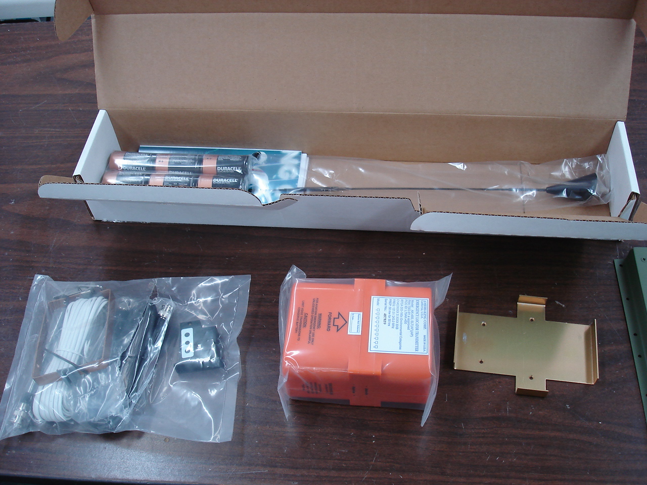
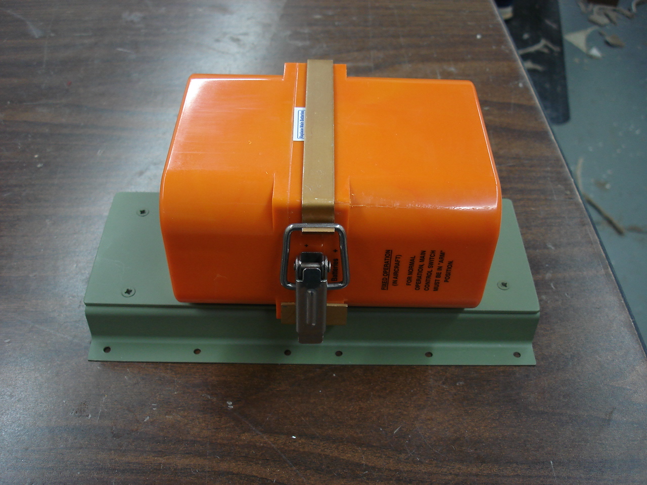
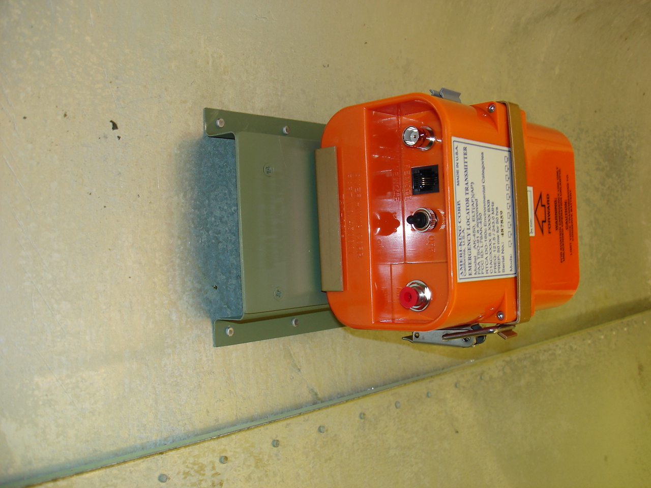
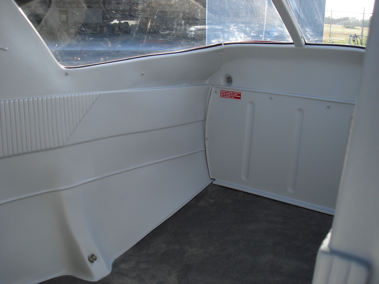
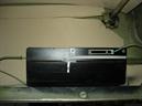
I tried to locate a photo of the old ELT location and I must have missed it. Anyway, the photo to the left is the actual unit which is an EBC model. This unit was installed on a bracket attached to the left side plastic panel in the baggage compartment. Lots of stuff to do here. First off, its a bad location. This area is prone to subjecting the ELT to getting hit by baggage, etc. when loading and unloading the airplane. Plus, it just plain looks tacky. Second, is that its an EBC. These units are old and have always been prone to leaking batteries causing the unit to set itself off for no reason while just sitting in the hangar. Also, they are extremely prone to hair-trigger activation. So out with it, and I shop for a new one. I chose the Ameri-King unit for several reasons. This unit uses Duracell flashlight batteries. You can purchase the batteries locally and whatever date is on the batteries is automatically your expiration date for the ELT . You still get to keep the value of the old batteries for use in your flashlights, kid's toys, or whatever. No more need to order special $50 battery packs. Thank you ! Also, its the full kit. Comes with the external antenna, mounting bracket (but not the base), potable antenna, remote switch and cabling. The other thing about this one is that it has a built in mic jack which is a feature found on the more expensive units. The importance of this is that in case you can't find the farmer's daughter and your cell phone is out of range, you can at least holler for help on 121.5 provided you carry a microphone in the plane.
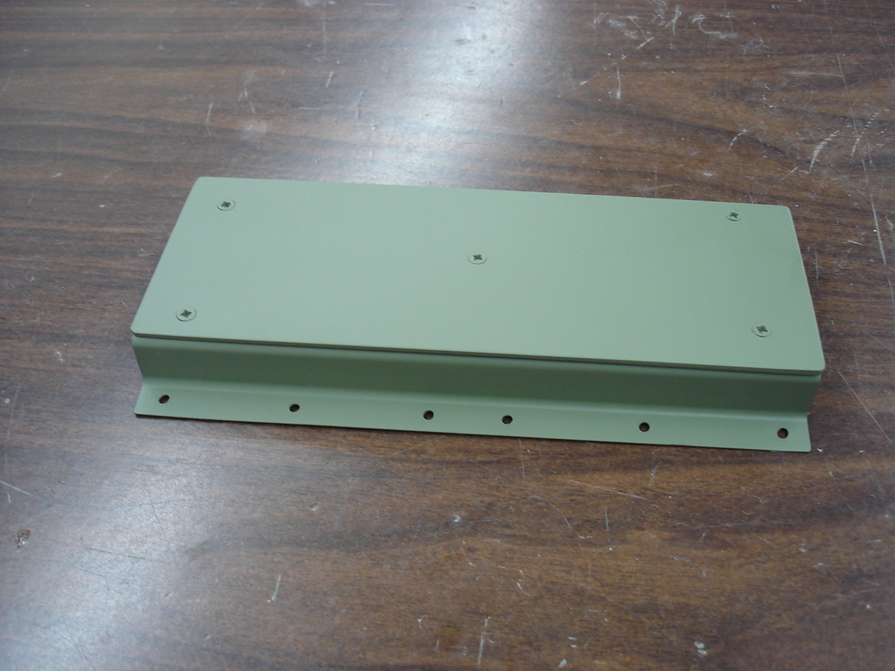
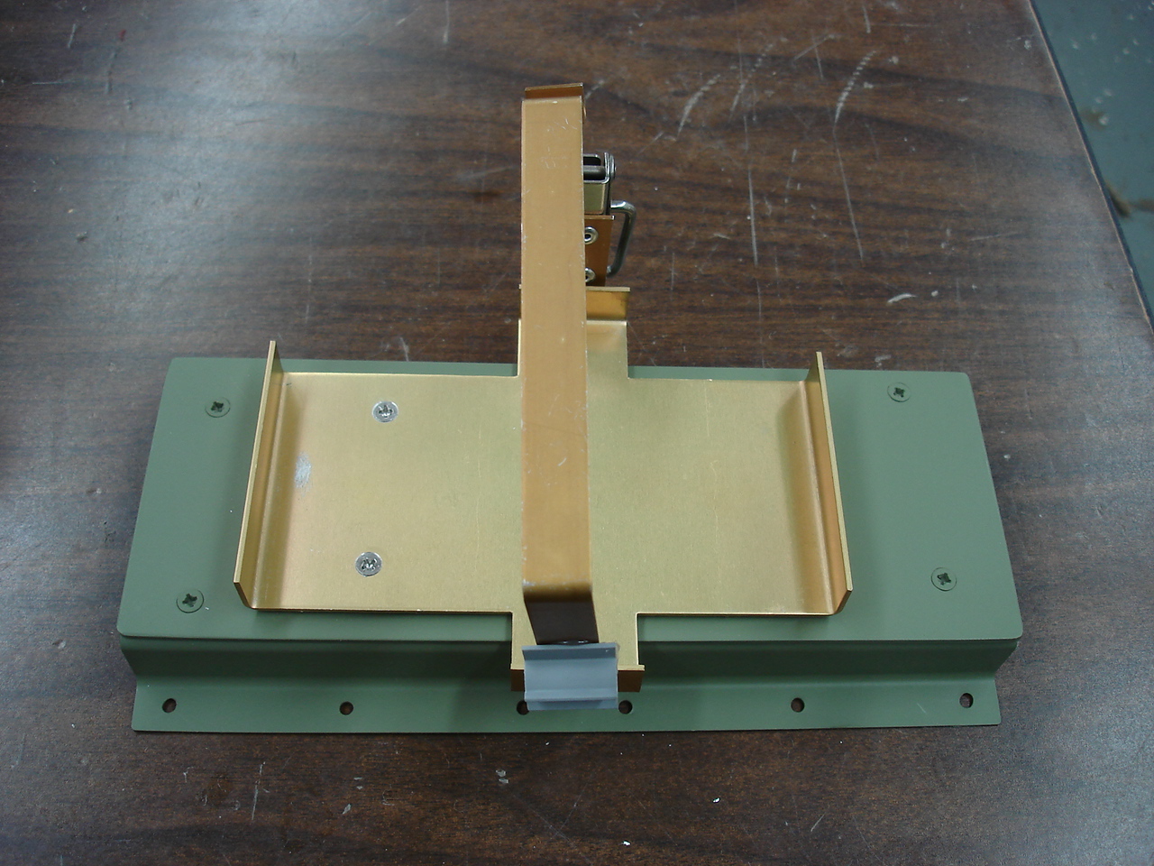
Also, I got an ELT mounting base for the Cessna 150/152 to put it on. Had to fabricate an adapter plate to go on it in order to provide a way to mount today's ELT on yesterday's mounting base. In the third pic, you see what it looked like after I made the adapter plate and primered the whole deal. Next, you see the ELT mounting bracket supplied with the unit, and then you see what the whole thing looks like when installed. It'll be behind the aft closeout panel mounted in the same location as Cessna uses. This plus having today's TSO C91A compliant unit for about $30 less than it's nearest competitor is about the best we can do here. As always, we hope it never gets used !


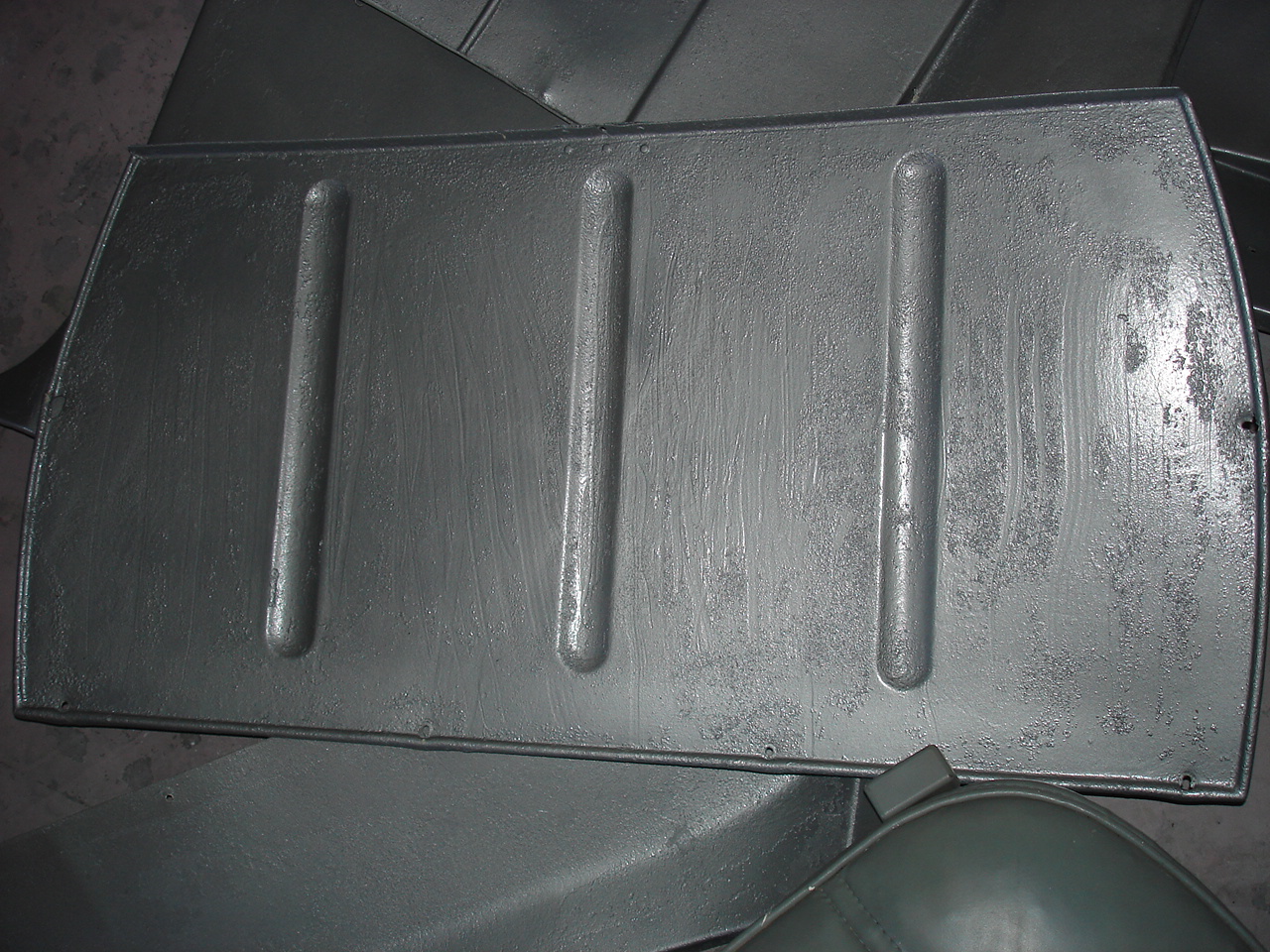
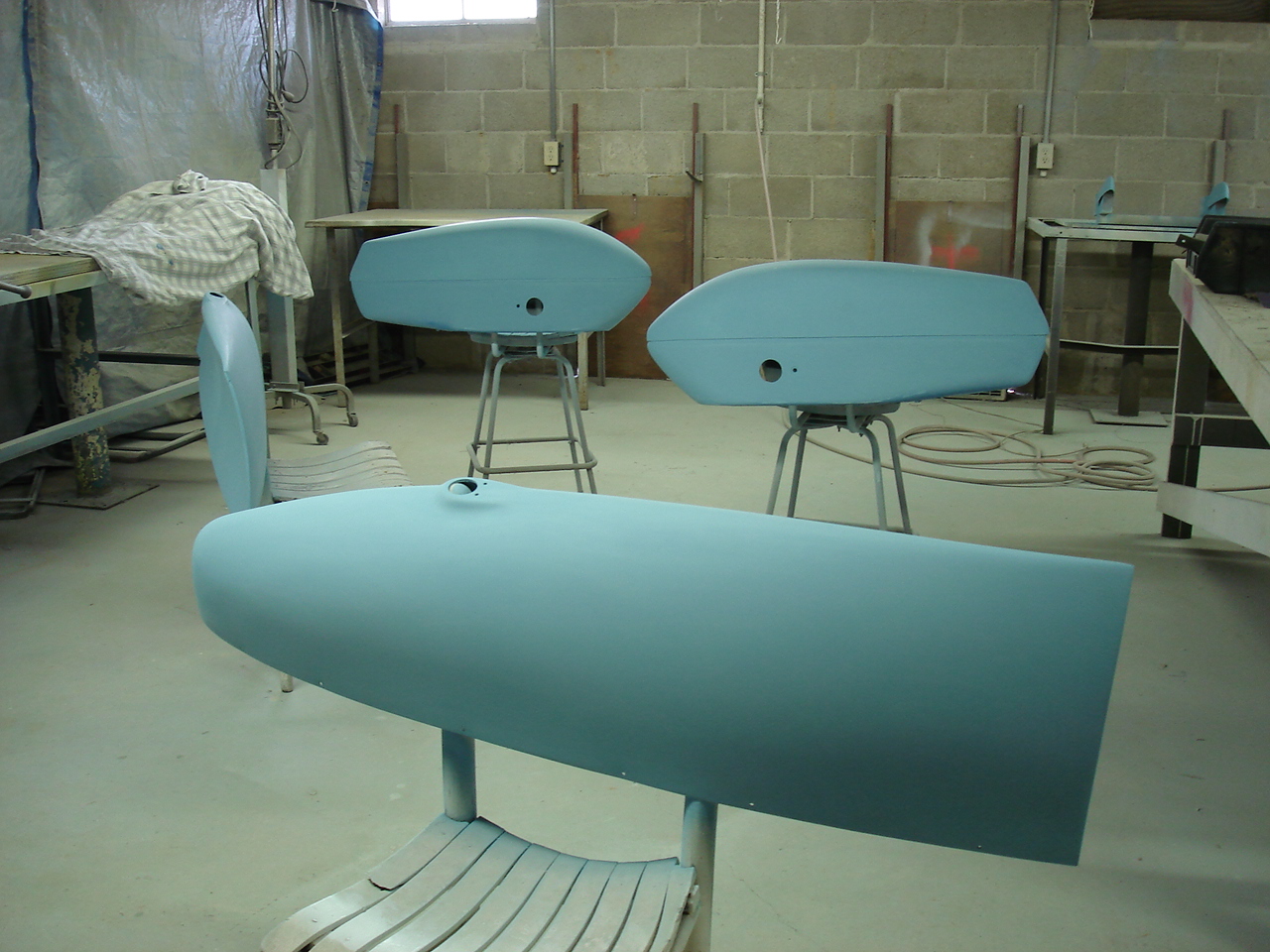
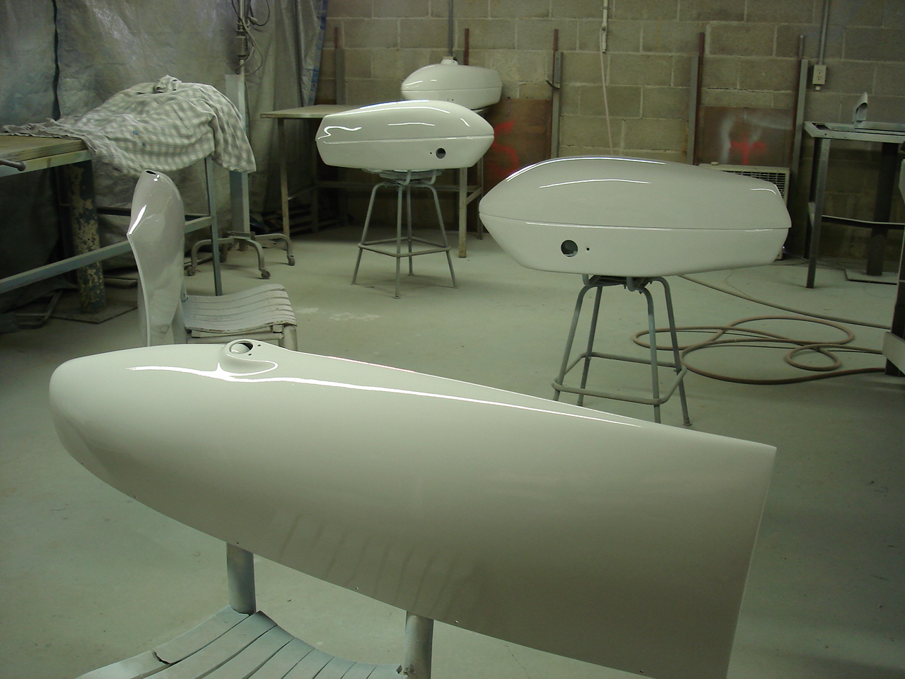
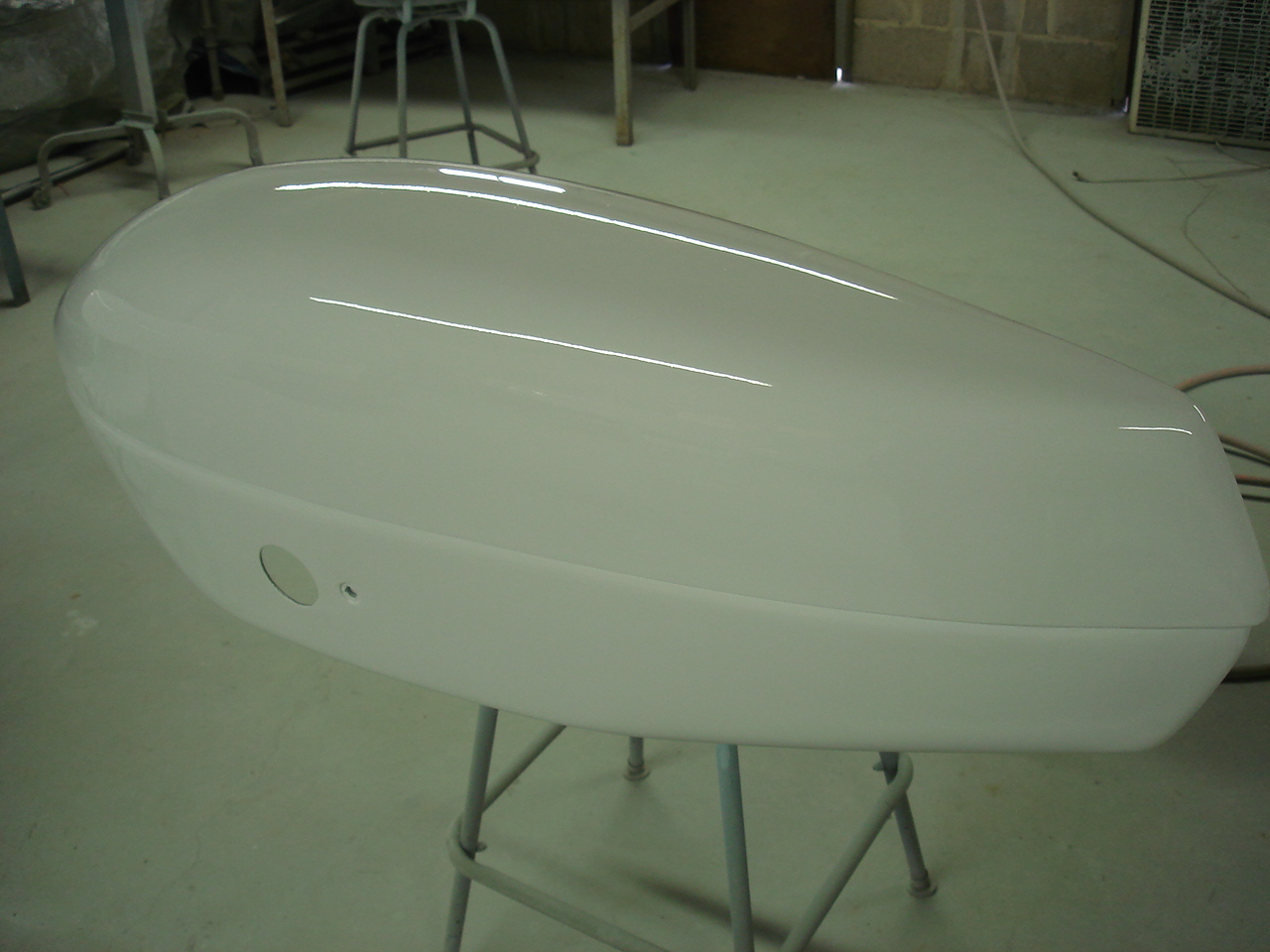
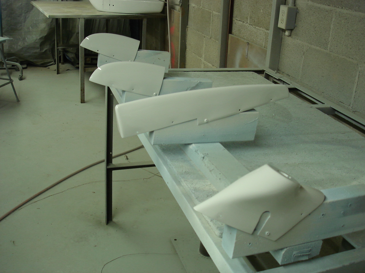
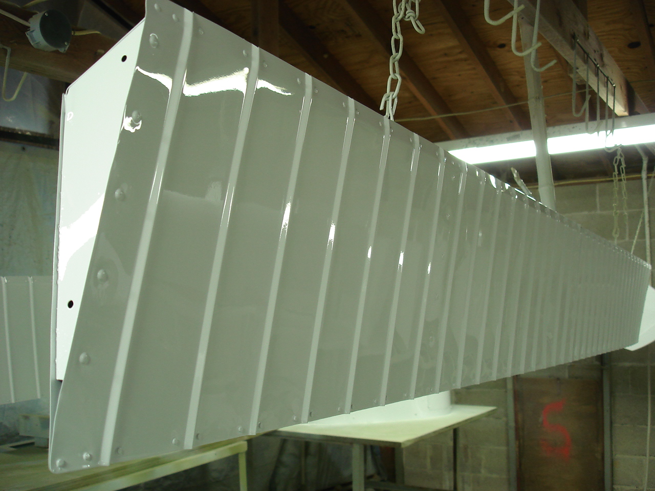
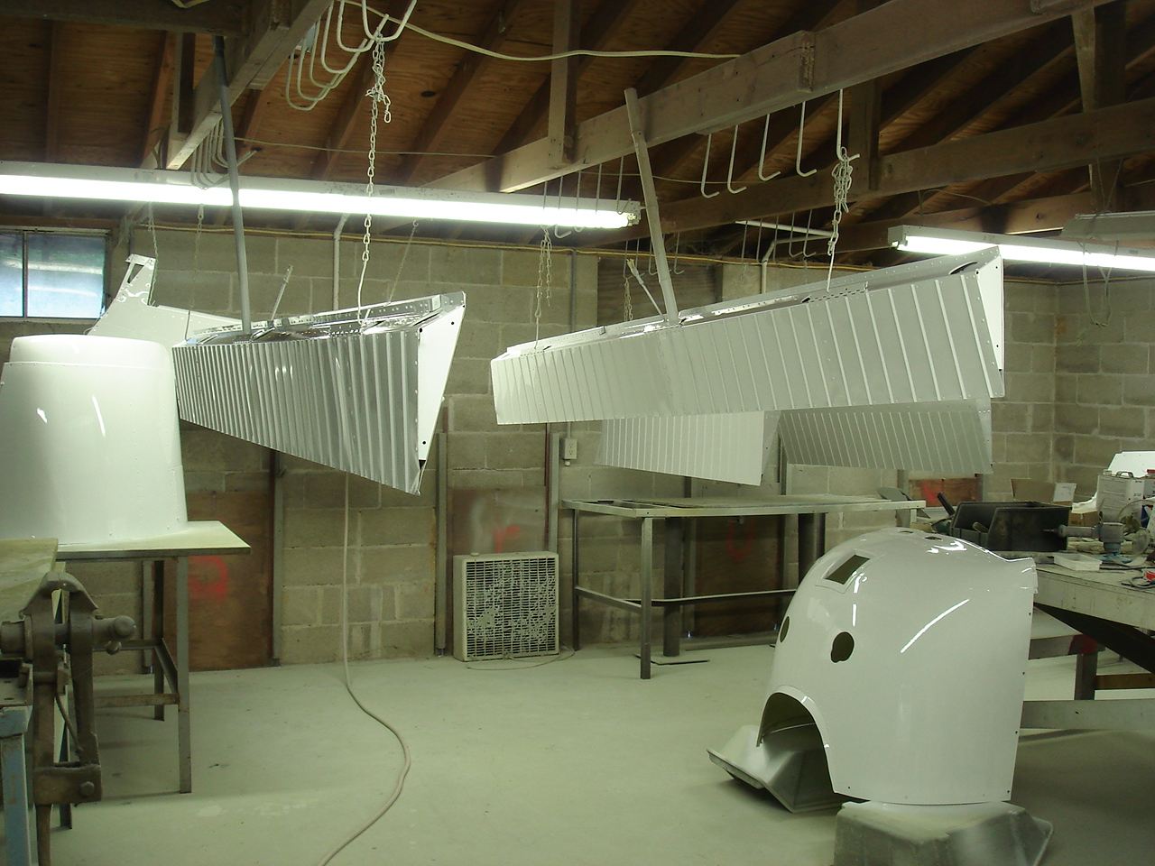
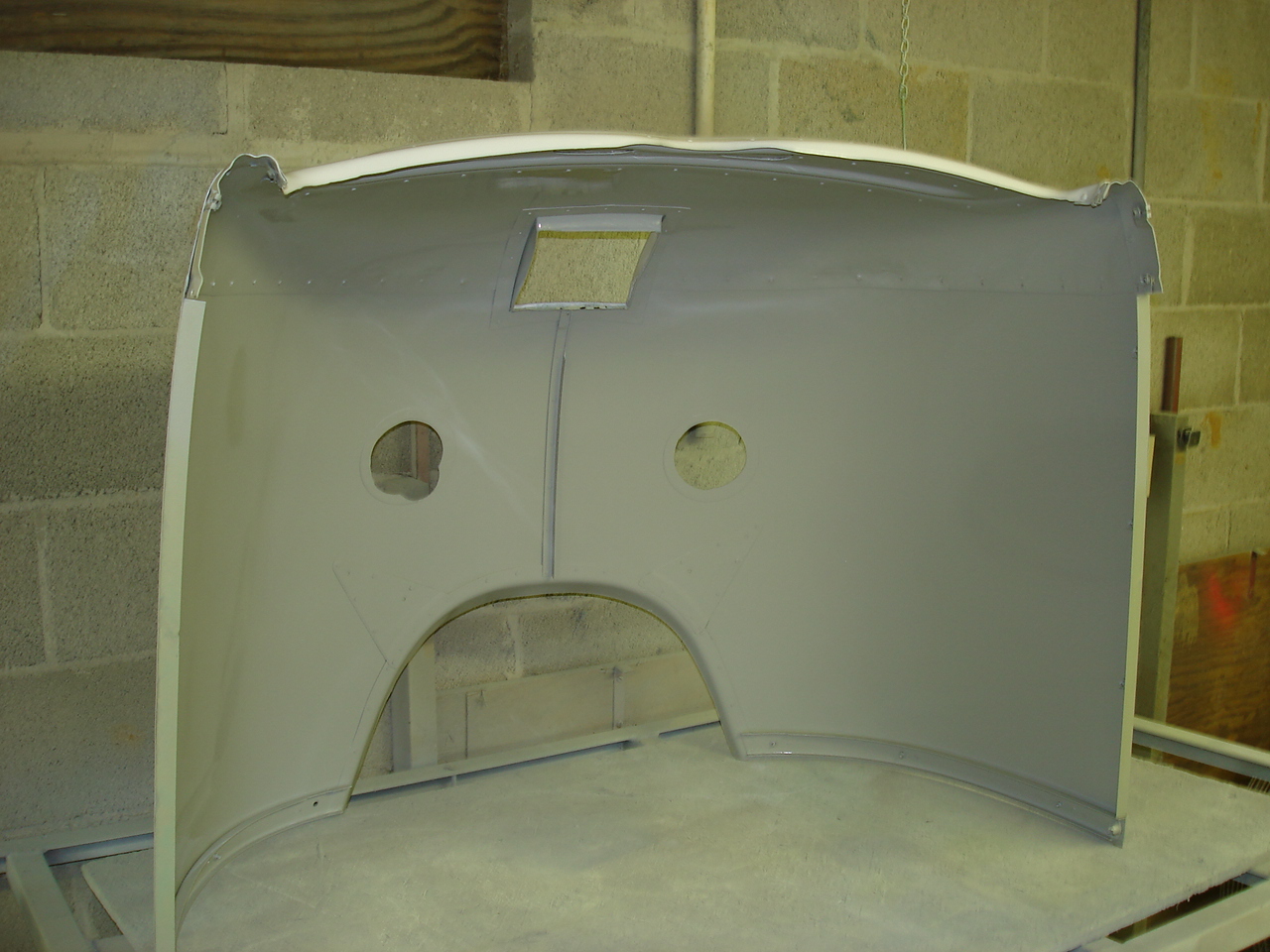
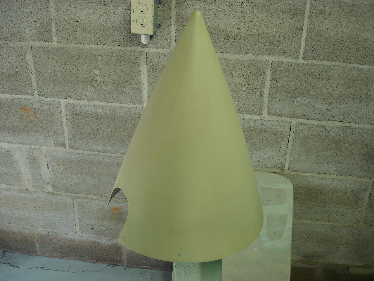
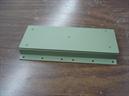
Here we start the prep work on all our bits and pieces. The first pic shows the original parts all sanded and ready for primer. Second one shows the parts primed with Jet-Glo epoxy fill primer. I really like the fill primer not only for its robin-egg blue color but is performance. Sands very well as you can see. Jet-Glo developed this primer especially for composite, fiberglass, and plastic components (also at the strong encouragement of the Beech Starship project). After letting three coats of Jet-Glo Matterhorn White do its thing we come out with some nice looking parts.

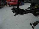

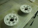
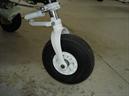
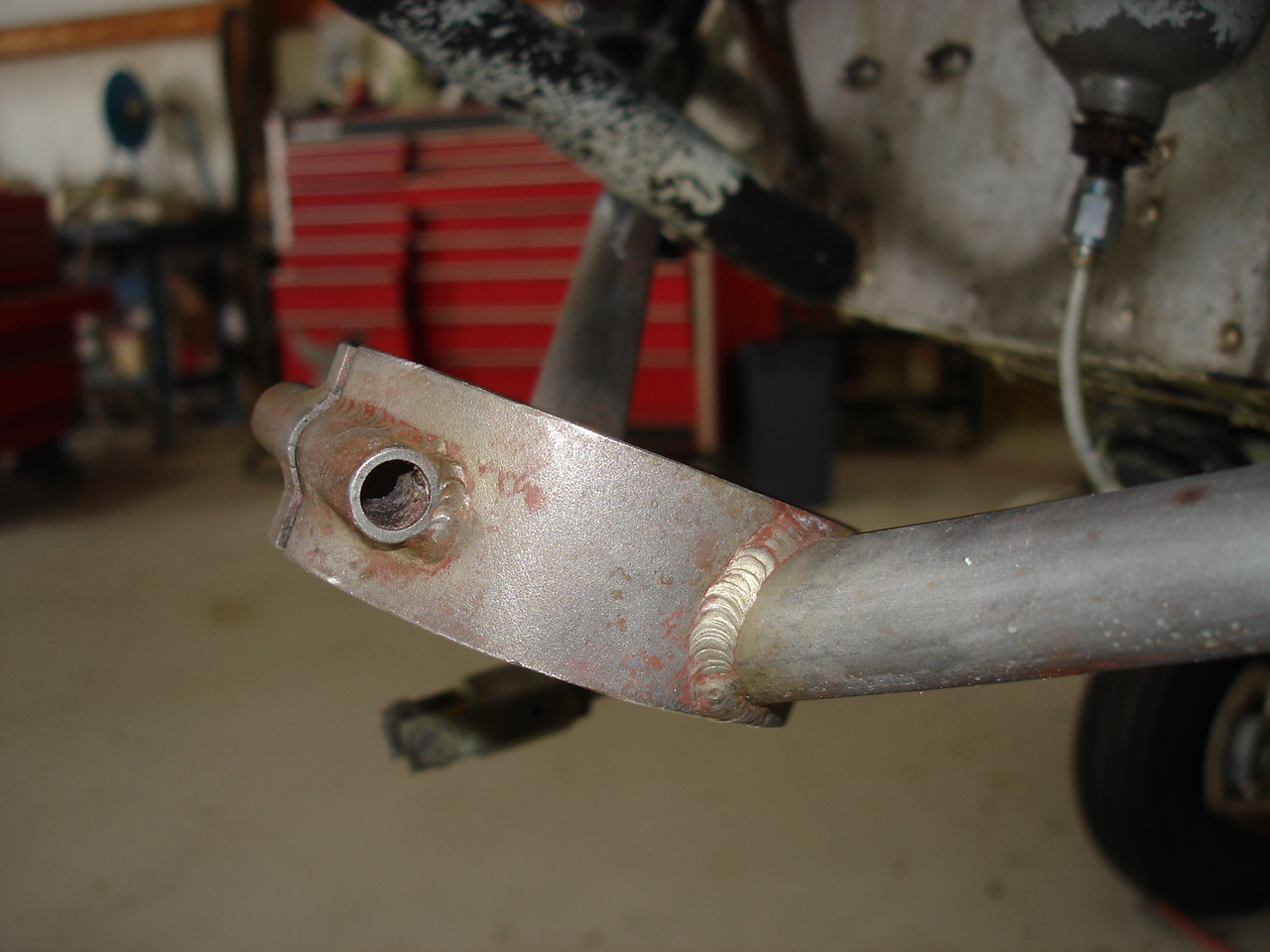
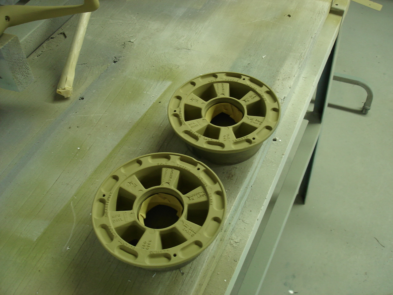
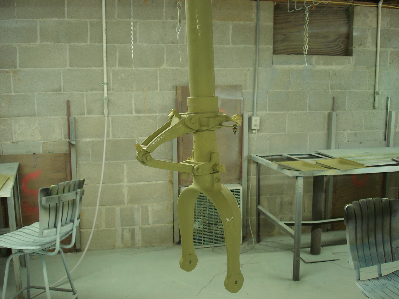
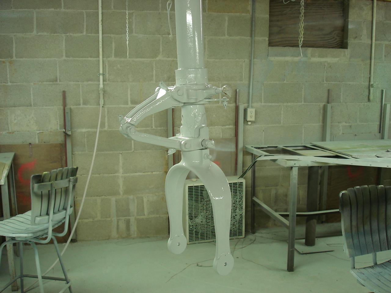
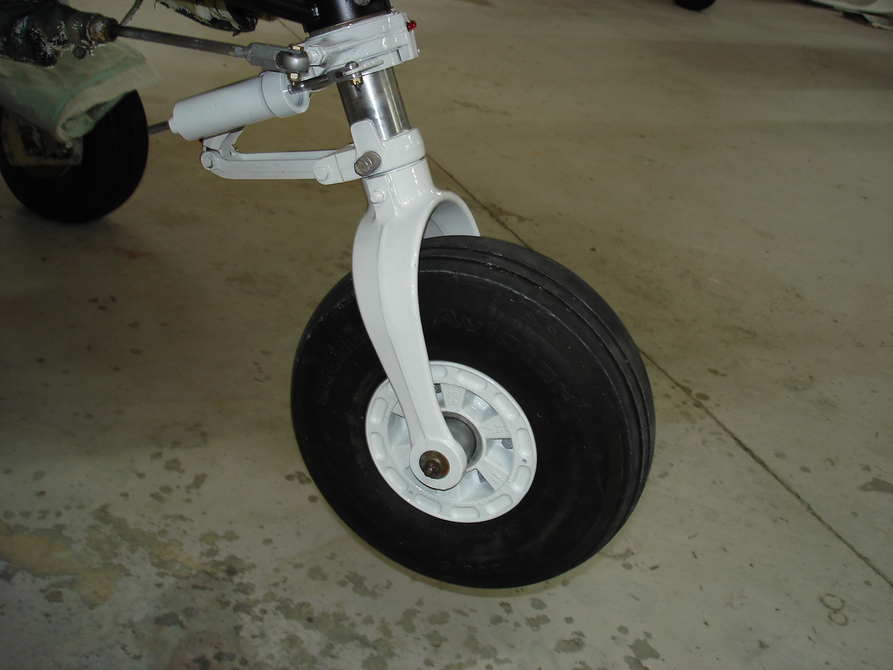
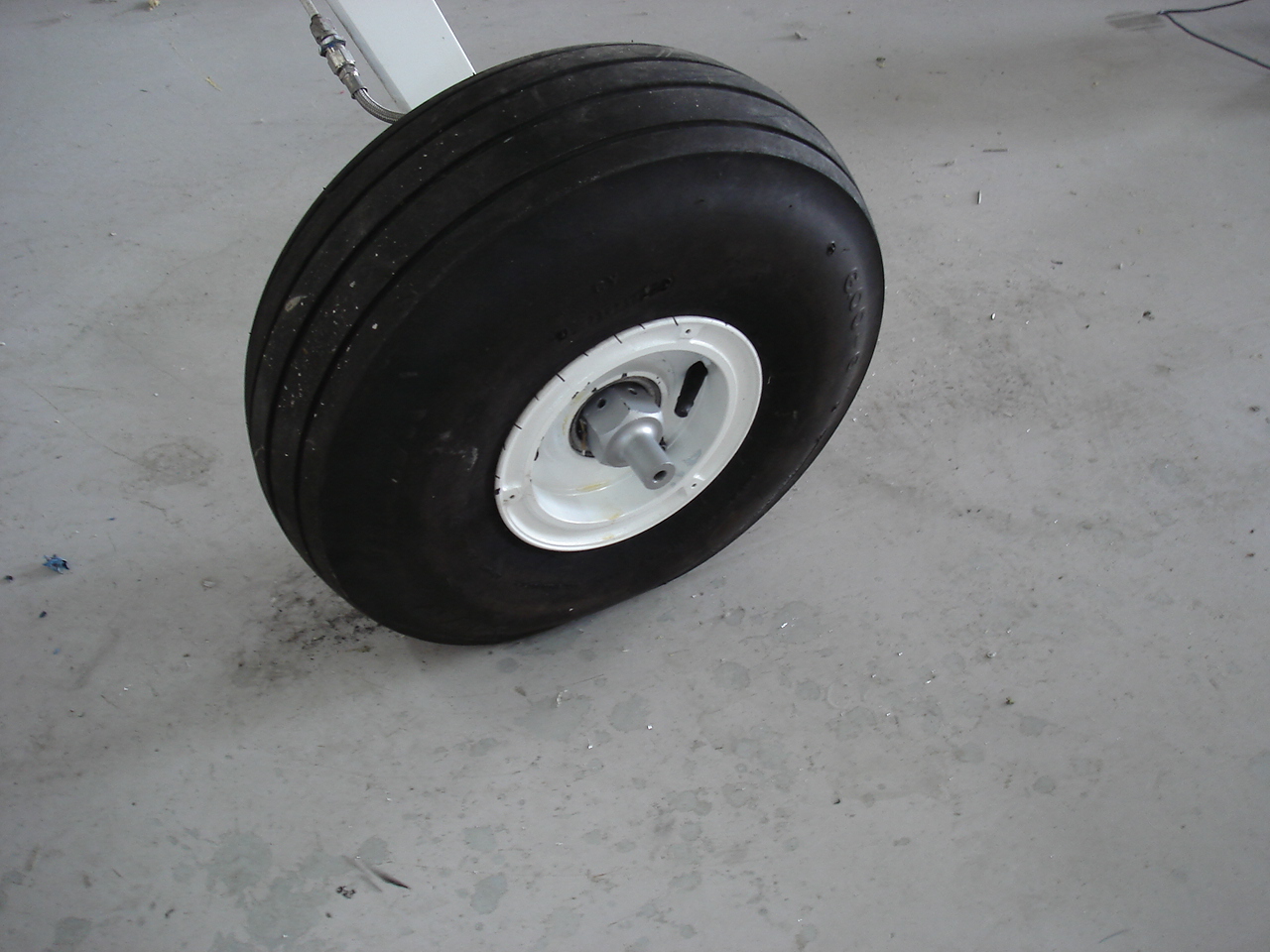
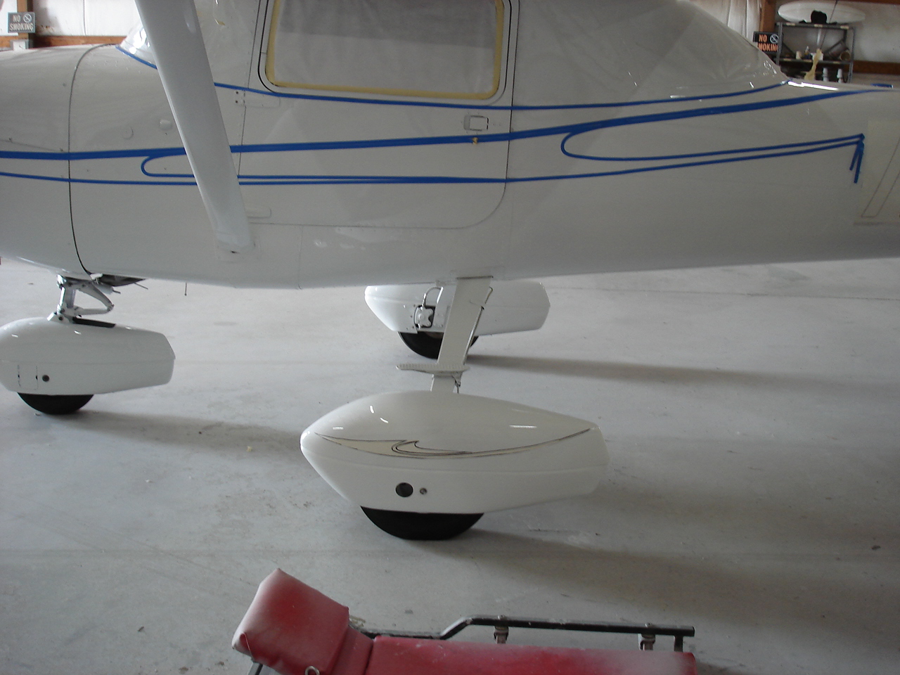
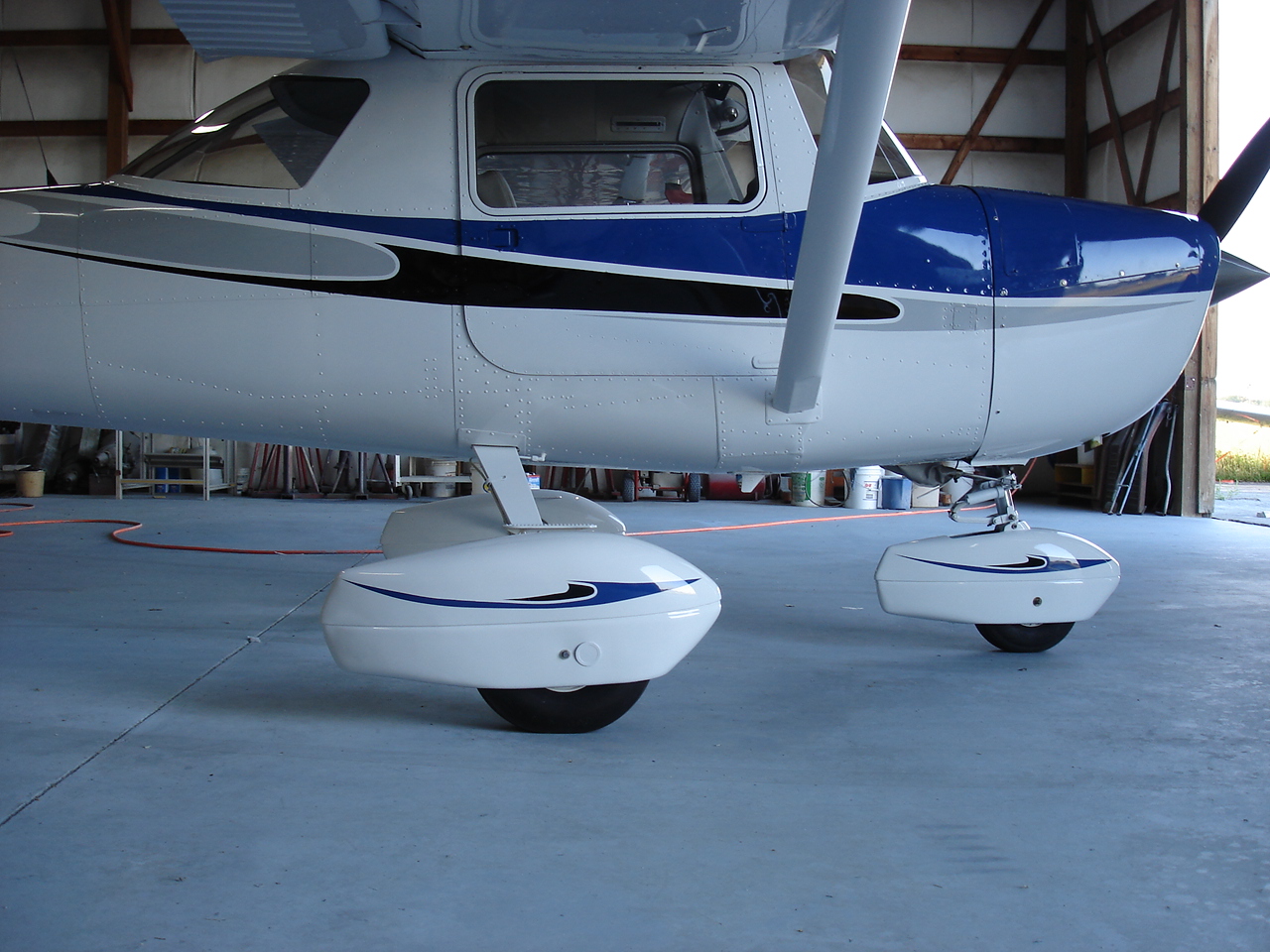
Down to the landing gear and wheels now. I cleaned the nose gear down and found numerous problems here. The torque links were loose and the steering collar was flopping up and down just to name a couple. The gear had rust that stuck it so tight I thought I never was going to get it to come out. But, I finally got it out and this gave me a good opportunity to inspect the lower engine mount tube. Loose nose gears and nose gear shimmy can cause cracks at the welds especially near the lower collar. The first picture shows what it looked like after removing the four or five layers of paint that was on it. Looks really clean now, so I primed it up and painted it back low gloss black. Next, I cleaned the nose gear down and installed new shims in the steering collar. Nice and tight now. On reassembly, I added some shims to the torque links, serviced the shimmy damper and re-installed it (using the correct hardware this time). Go to the paint booth and primed and painted Matterhorn to match the plane. Dismounted the nose tire, cleaned, inspected, primed, and painted the wheel halves. Cleaned and repacked wheel bearings and reinstalled. I'll save the install of the nose wheel pant for later. A lot of labor here, and a very few inexpensive parts but all in all well worth the time and trouble. Wouldn't want a shimmy shaking my new panel and all those overhauled instruments. Not to mention causing the passengers unnecessary anxiety and high blood pressure. Looks almost brand new now too.

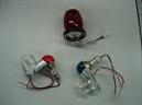

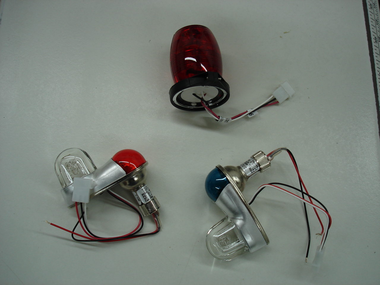
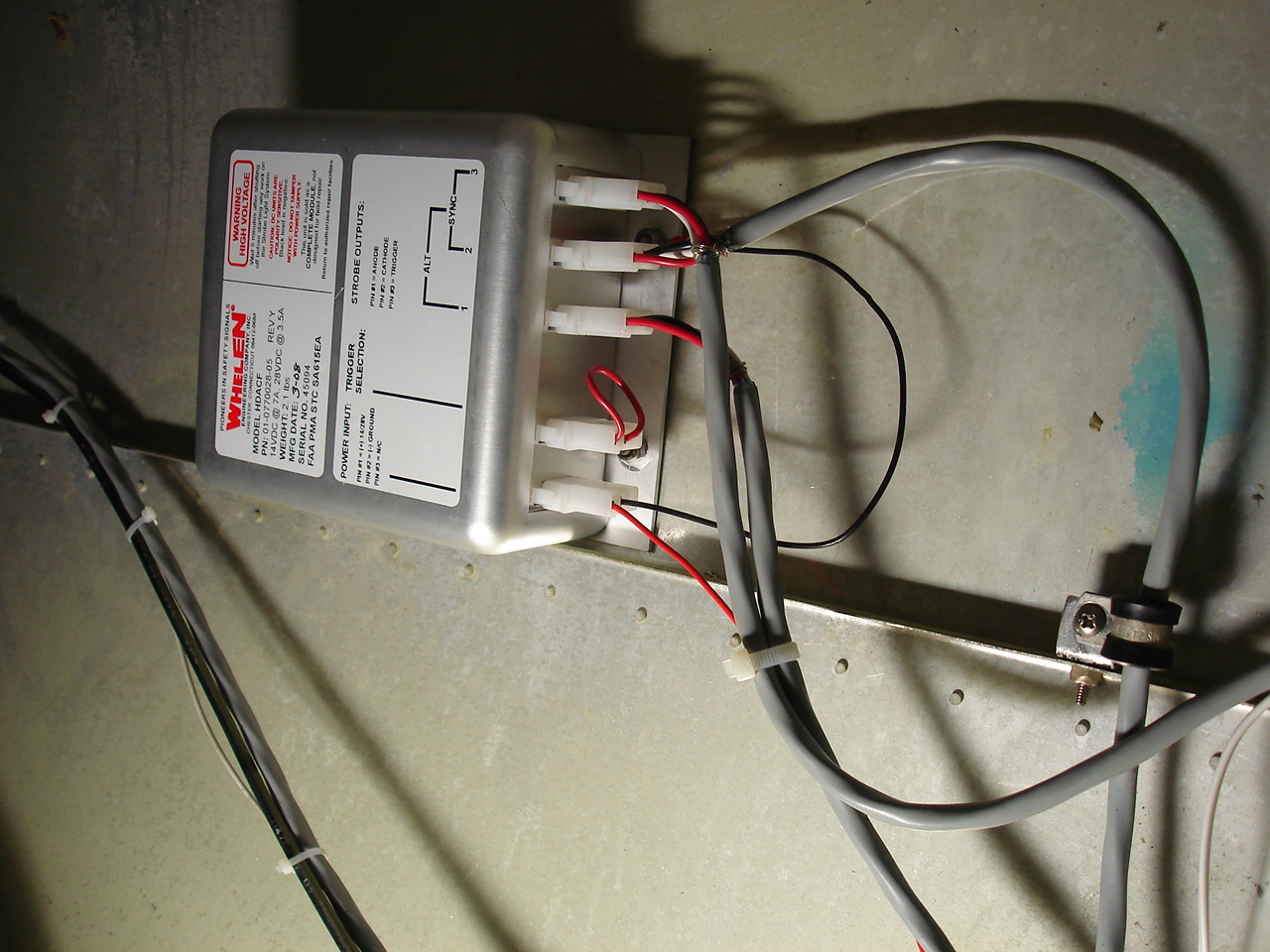
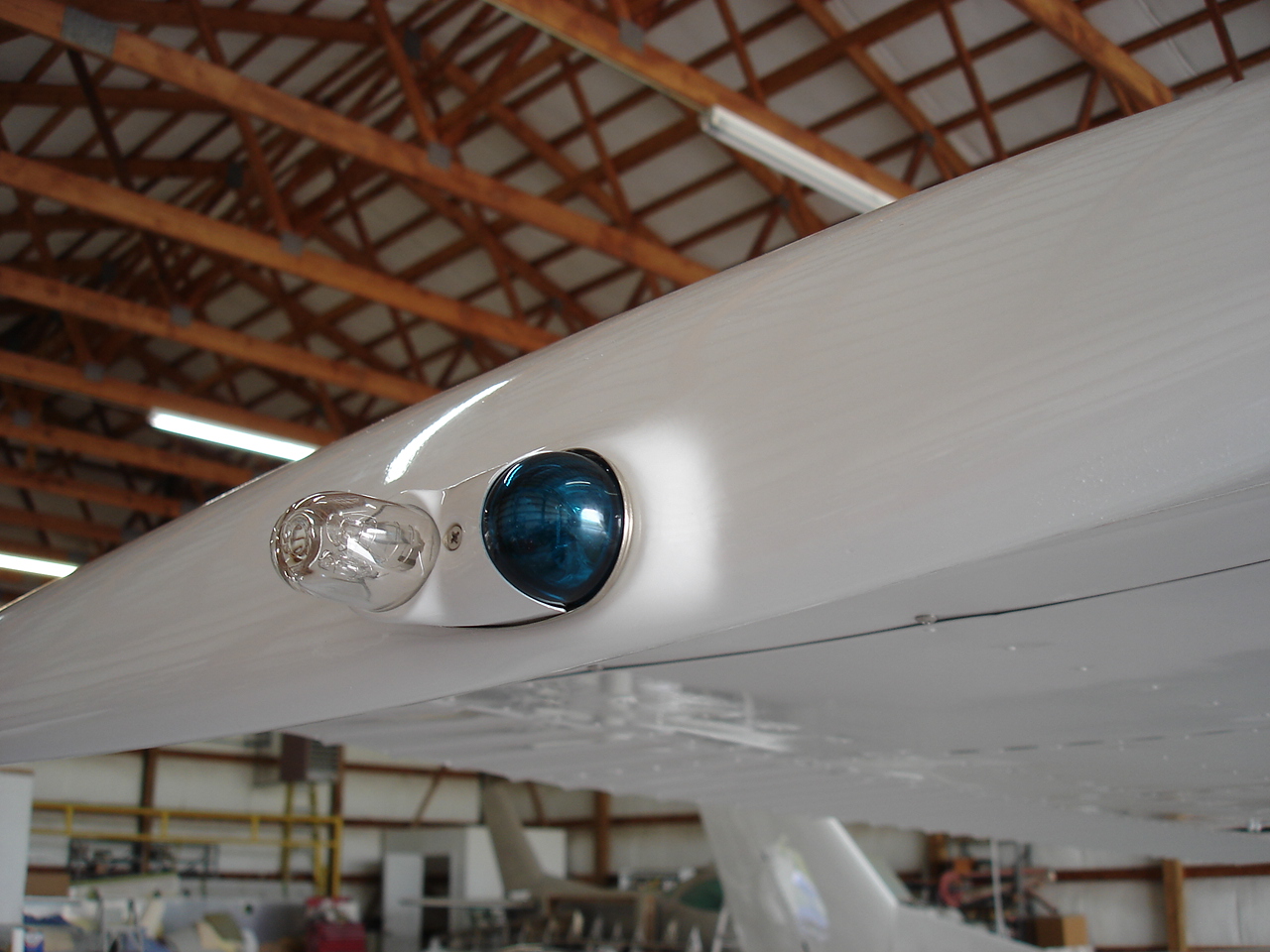
When it came down to adding strobes, I had to decide which ones to go for and how much to do. Didn't really take long to figure out that the best route to go was the complete nav light and strobe combination. The first pic is of the old nav light assemblies. Thick layers of old paint and generally ratty looking sockets and wires. The new nav light/strobe assemblies come with new sockets, lenses and all. There's nothing quite like new nav light sockets, lenses, and bulbs to make for some bright lights. Got all the strobe harnesses run for the wing tip strobes and also for replacement of the beacon with a Whelen strobe. Available in aviation red or white, so we pick the red. The whole deal runs through one flasher assembly so we don't have to worry about replacing individual flashers in the wing tips or tail.
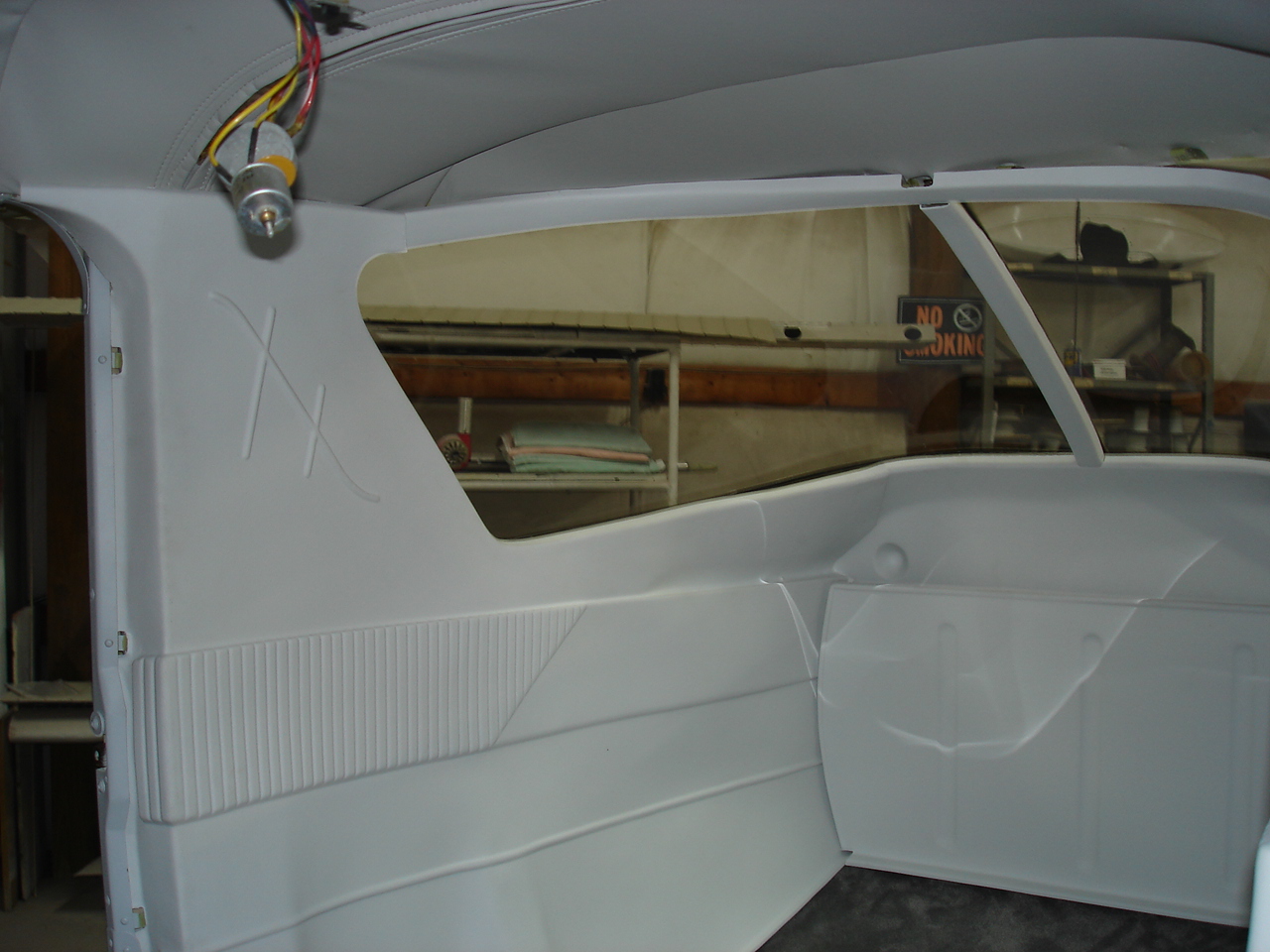
Got all new plastics, which means we basically buy us something to work with. Lots of cutting, filing, trimming and fitting. The second picture shows (sort of) how it looks during a mockup to see how much more we have to do. Pretty much have it where we want, so we'll drill all the holes, screw it in place and basically do a full install. Next, its completely removed, cleaned, primed, and painted with Jet-Flex Grey. More pics of this to come.
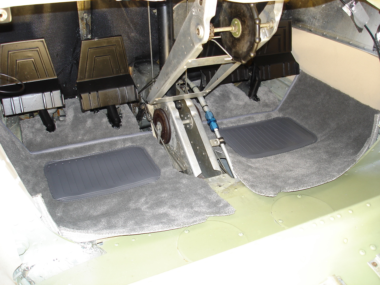
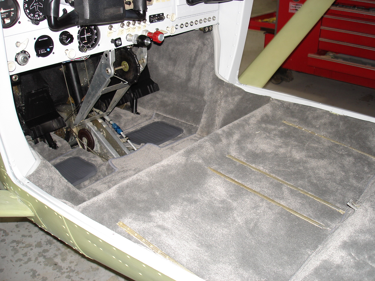
A minor detail here, I know, but something we wanted to do. Most all 150s and 152s have painted close-out panels. On this one, we added a bit of a custom touch by carpeting these as you see in some of the larger aircraft. This gives the illusion that the carpet goes all the way to the firewall. We hope nobody looks that close, but we'll do it anyway. Also fitting the foot pan carpets and the side kick panels as well.
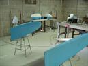
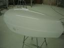
Well the big day comes to put the paint to it. Also painted inside the engine cowl light grey. The whole airplane begins to suddenly change.
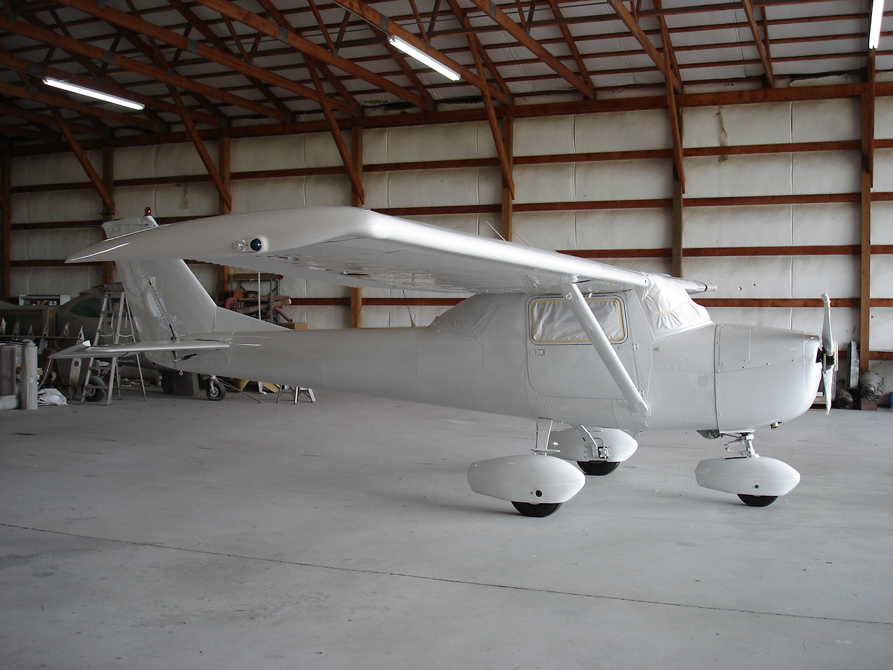
Assembly operations are now underway in these photos. All the parts that have been worked up individually are now installed to complete the aircraft. Wing tips, strobe lights, wheel fairings, etc.
Next, the design work begins to get the paint scheme we want. Takes about 10 solid hours to complete a design layout like this. Plus, took some extra time to add some "one-off" accents to the wheel fairings and wing tips. Had to sort of make this up on my own using some (I guess you could loosely call it "sketch art") methods to get to where I want to be with it.
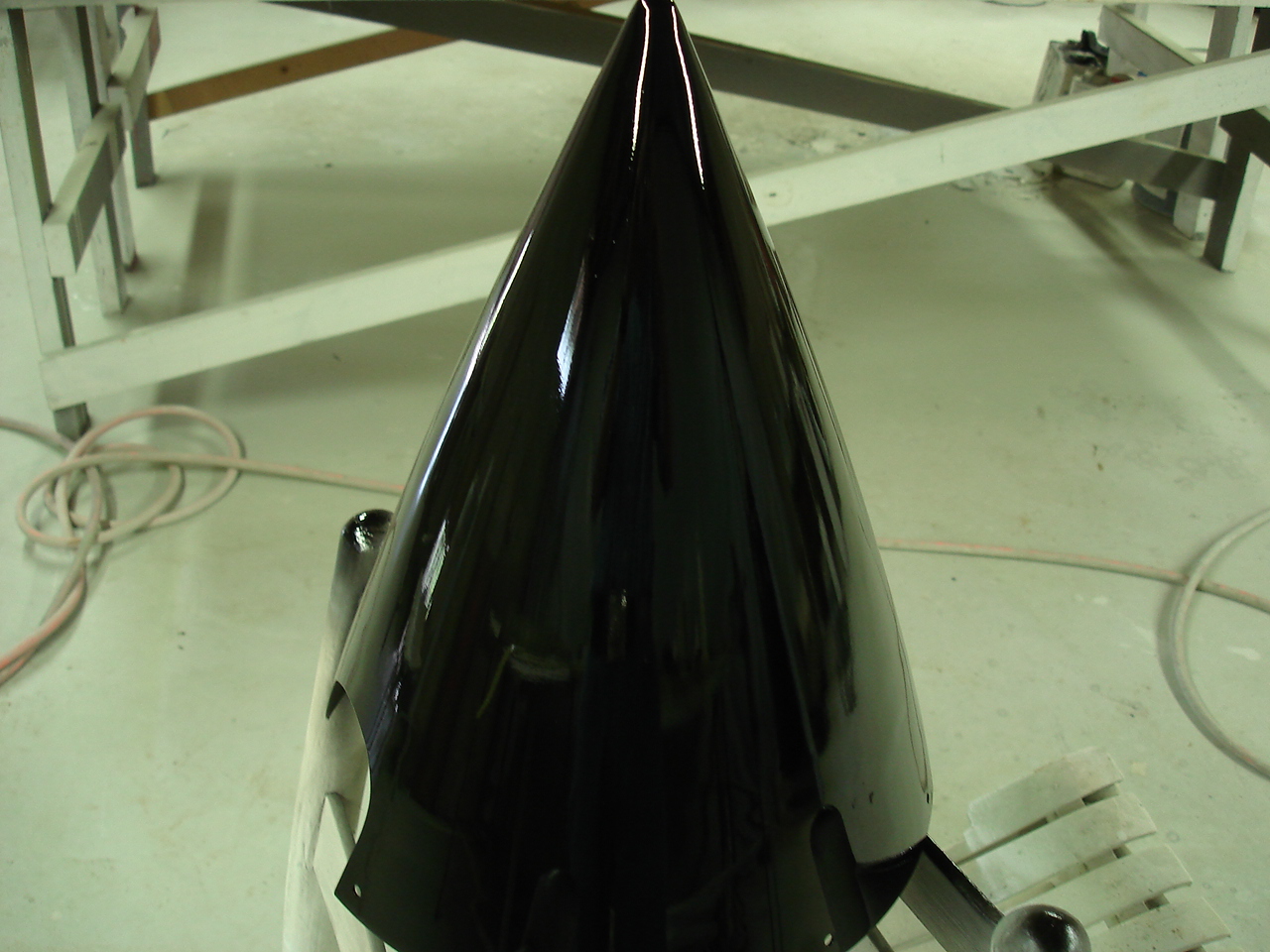
One...two...three....CHROME !!
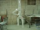
Not exactly, but as close as we can legally get on a Cessna spinner. What I did here was a fairly new process to add a "chrome effect" to the paint job on the spinner. The metal treatment, primers and all are the same process as the rest of the aircraft. The main difference is the spinner has to be painted in a polyurethane black to a smooth, glassy finish. After a 5 day cure time, the spinner is then painted with the chrome effect. The science is kinda sorta like a mirror. The black background give the item depth and the metal in the paint reflects the light back out of it. I can dig it.
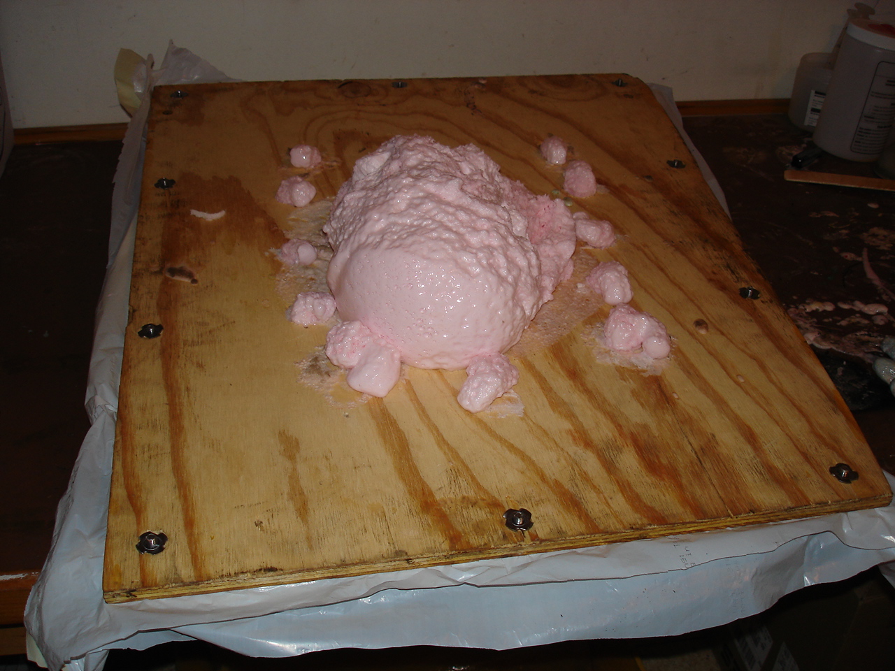
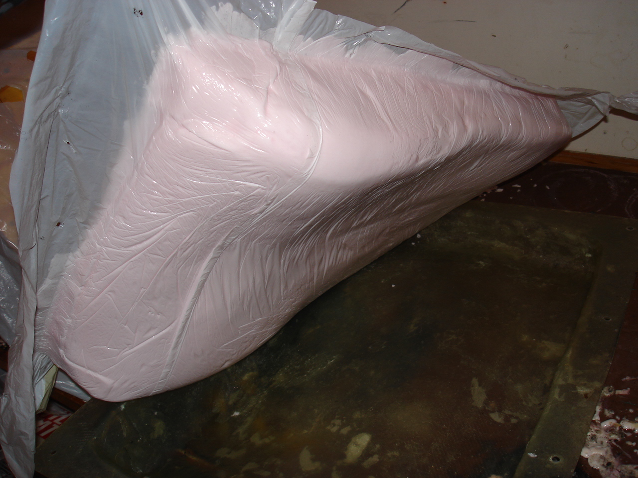
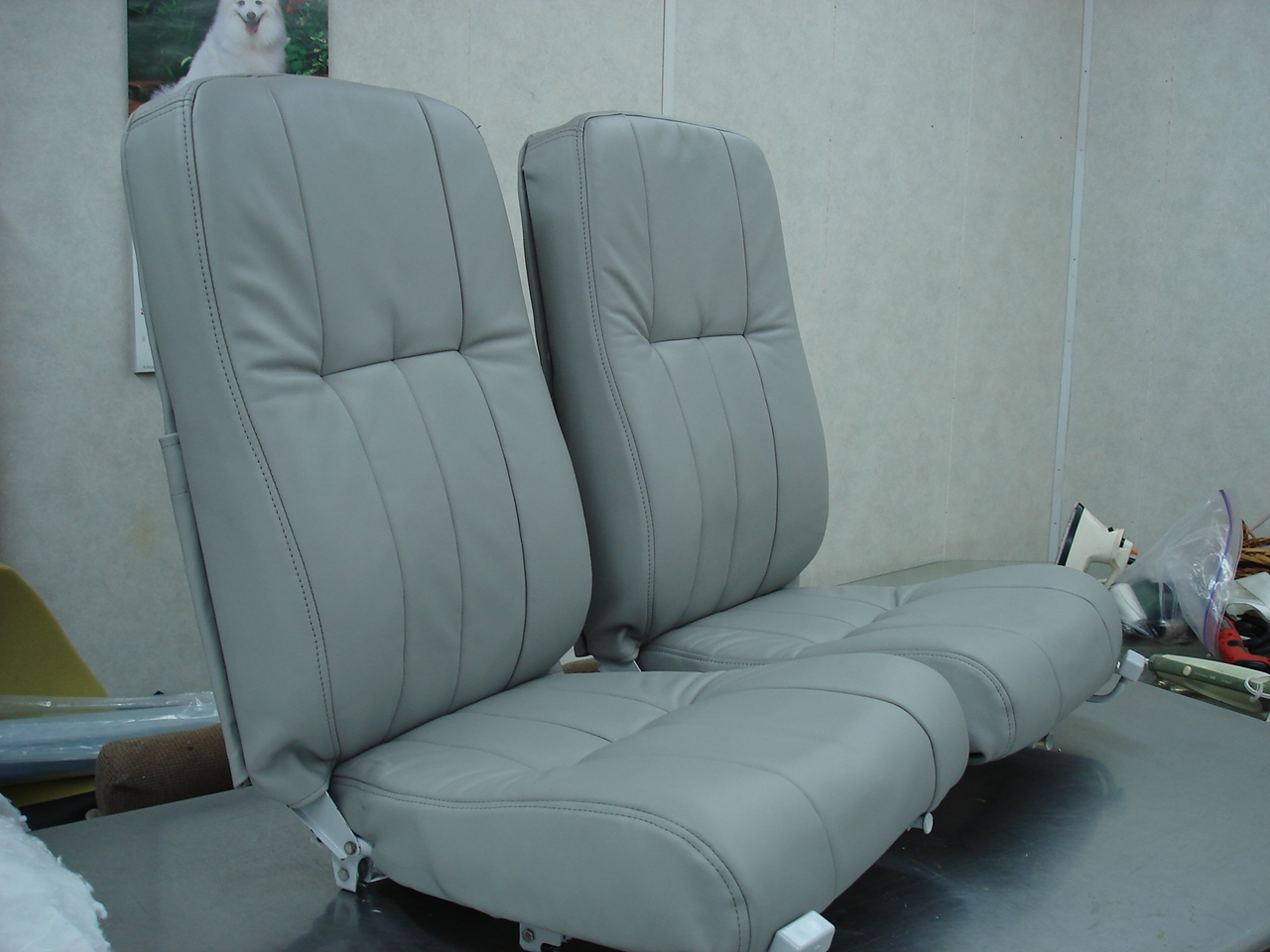
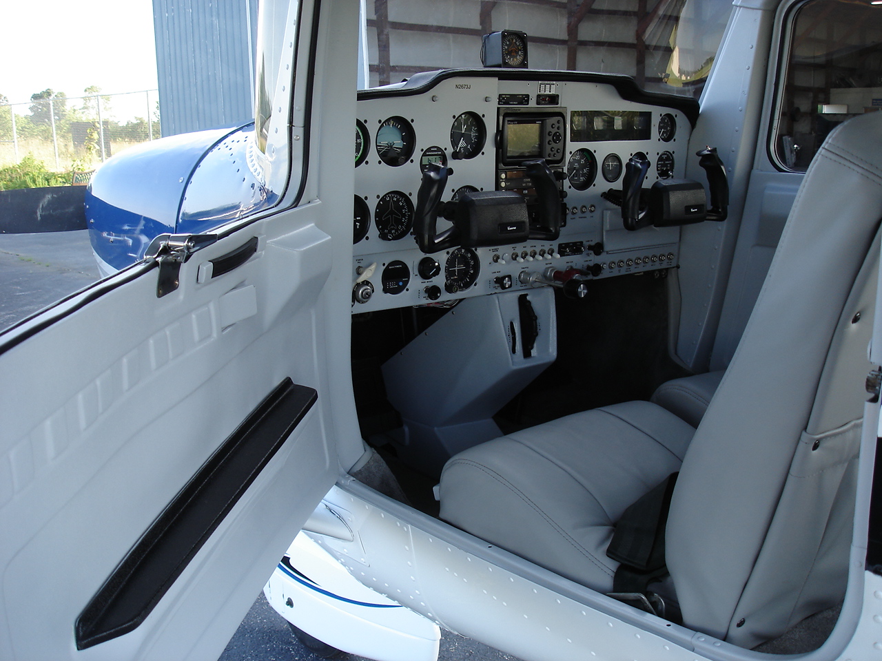
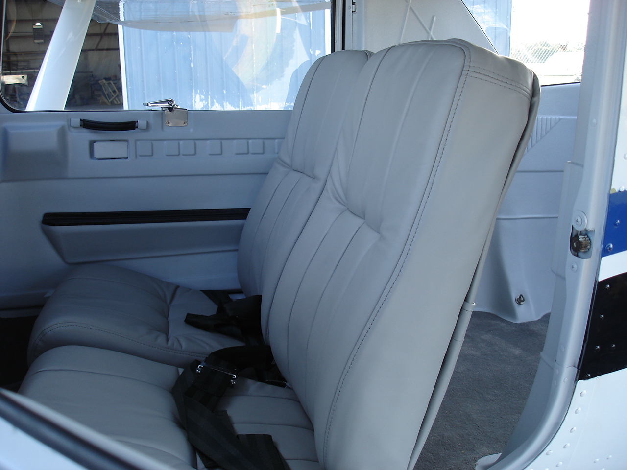
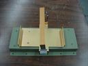
Another custom process I used on this one was the solid-core molded seat cushioning. What I wanted here was body-forming confor foam seating contoured for support to the lower back and behind the legs. After I built the mold to fit our frame design, I came out with a seat that is low in the back, high in the front, and keeps the lower back supported. Finished it off with some Fine Scottish Leather with top stitched seams. Oh yeah.
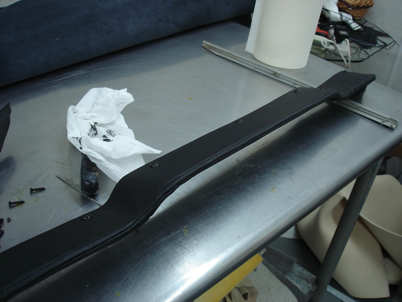
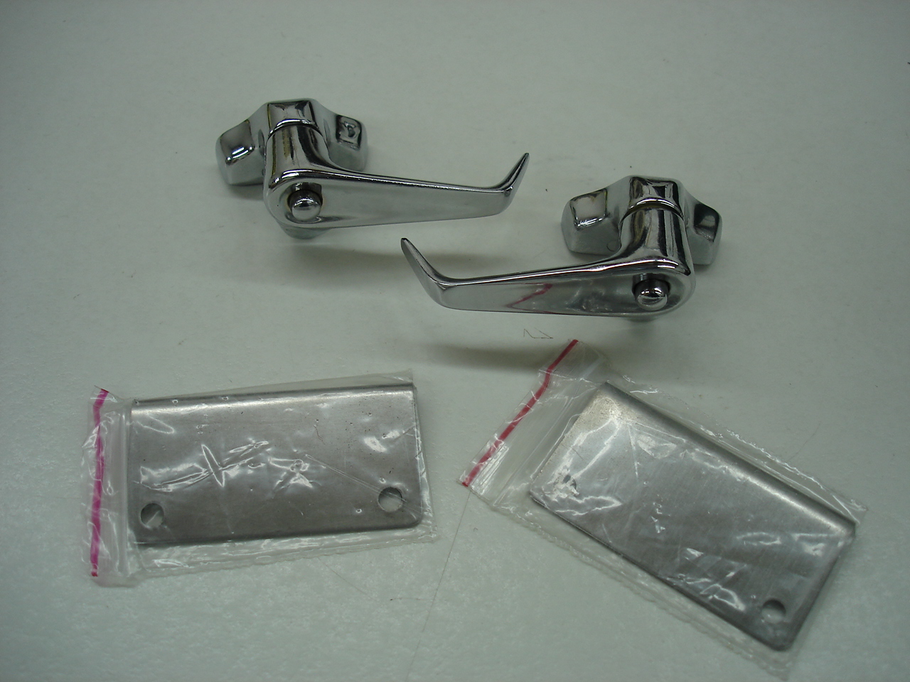
Now we begin to trim it all out. Adding an absolute ton of work doing little tiny details like adding door pull handles, some new chrome window latches, a custom fitted leather eyebrow and some new interior plastics.
Well now we can see what we came out with. Use a few varying designs such as the Skylane-style paint scheme altered to fit the 150, and an interior and panel that now resembles the twin-Cessna 340 and 421 business aircraft.
And now for the "Before & After" shots !!
Before After Before After
Before After Before After
Hope you enjoyed the photos. Thanks for visiting !!!
1967 Cessna 150G